Slew-Rate Control Reduces EMI
You can reduce the high frequency components of square wave signals
by slew-rate-limiting their logic level transitions
On this page we show how slew rate limiting signals can reduce radiated emissions (EMI and RFI) from your computer based product by reducing the harmonics of its digital signals. We'll explore the sources of the upper harmonics in the spectra of digital pulses so we can implement methods for reducing their intensities, and thereby reduce radiated EMI and RFI. Fourier analysis of unsymmetrical square and trapezoidal waveforms shows their frequency spectra.
Harmonic spectrum of a square wave
Many digital signals resemble a square wave. Consider the ideal square wave shown in the Figure 1. Only one cycle of the indefinitely repeating waveform is shown. It is ideal in the sense that the transitions from one logic level to another are assumed to take no time at all.
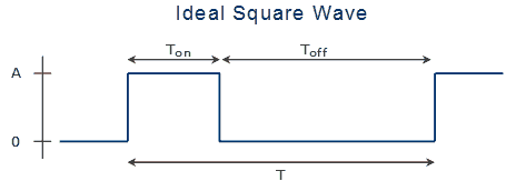
The waveform has several important timing parameters that determine the spectral envelope for EMI (radiated emissions):
- The overall period, T. The fundamental frequency is the inverse of the period, that is, F1 = 1/ T.
- The on and off times, Ton and Toff. For a symmetrical square wave the on and off times are comparable, and both equal to T /2
- The amplitude, A.
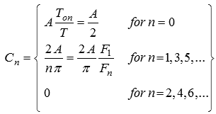
To determine the spectrum, or frequency components of this waveform, we can decompose it as a Fourier series of additive harmonics. Fourier analysis is a method for representing any repetitive waveform as a sum of sine or cosine waves of frequencies, Fn, that are integer multiples n, or harmonics, of a fundamental frequency, plus a zero frequency component equal to the average value of the waveform. The magnitude of the n'th sine/cosine frequency component we designate as Cn.
For a square wave, the DC, or zero frequency, component has a magnitude equal to the average value of the waveform, or the duty cycle times the amplitude, as,
The other components, or harmonics, are integer multiples of a fundamental frequency, F1, which is equal to the inverse of the waveform's period, as,
where the n are integers.
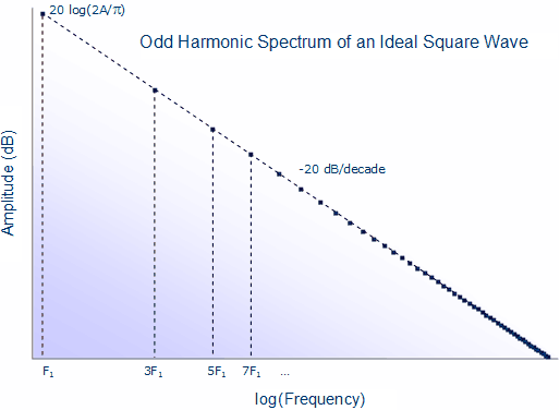
For a square wave with equal on and off times, that is, of exactly 50% duty cycle, only odd harmonics are present. The amplitudes of the frequency components fall off with frequency as,
We can view the fundamental frequency as a cut-off frequency, above which the amplitudes of frequency components falls off with inverse frequency. The 1/F fall off causes an amplitude reduction of the harmonics of 20 dB/decade, as shown in Figure 2.
Harmonic spectrum of an unsymmetrical square wave
For an unsymmetrical square wave (a square wave with duty cycle other than 50%) the situation is a bit more complicated. The cut-off frequency is now given by the shorter of the on or off times, as,
And the spectrum is not limited to the odd harmonics. The amplitudes of both odd and even harmonics now fall off as,
This equation is a more general case of Equation 3, but now for any duty cycle. At 50% duty cycle, that is, when Tmin/T = ½, the sine function is zero, and the even harmonics disappear. But even small deviations from 50% duty cycle cause the even harmonic content to vary widely.
An illustrative spectrum is shown in Figure 3, for a repetitive pulse train of either 10% or 90% duty cycle.
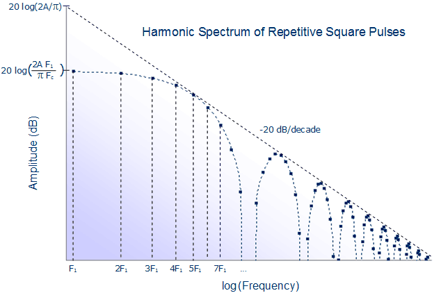
Note that for low frequency components, that is, for Fn < Fc, the amplitudes are constant, and given by,
while for frequency components greater than the cut-off frequency, that is Fn > Fc, there is a 1/F fall-off in amplitude, with a superimposed wiggle (from the absolute value of the sine function). Nevertheless, the amplitudes are bounded within an envelope defined by,
Note also that for this 10% duty cycle waveform, the tenth harmonic and its multiples are missing. This response is that of a classic low-pass filter with a sinc response (that is, with notches determined by the sinc or sin(x)/x function). For any repetitive pulse train, there are notches in the spectrum at all multiples of the frequency 1/Tmin. Where those notches correspond to the harmonics (i.e., integer multiples) of the fundamental frequency, those harmonics are completely absent. In the case of a 50% duty cycle square wave, the notches are placed at all even harmonics; hence their coefficients are all zero.
Harmonic spectrum of a slew rate limited square wave
Digital signals are not ideal square waves, but may be approximated by trapezoidal waveforms with finite slew rise and fall times, tr and tf. Because the rise and fall times are finite, the waveform's harmonic energy at high frequencies is less than that of an ideal square wave. Consider the following trapezoidal waveform with slew-rate limited rise and fall times, and its spectrum:
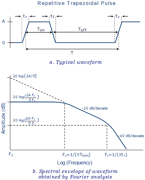
This waveform is characteristic of many digital signals, including clock pulses and PWM waveforms. Without much loss of generality, when deriving the spectrum of this pulse train we'll focus on the case of equal rise and fall times.
Fourier analysis of this trapezoidal waveform provides harmonic magnitudes similar to that for an unsymmetrical square wave, except that there is an additional term that limits the high frequency content. The harmonic amplitudes1) are given by,
Similarly to above, we can rewrite this expression in terms of frequencies, as,
Where we define an additional high frequency cut-off that depends on the rise time as,
The amplitudes of the harmonics fall off with respect to frequency as shown in the above graph (Figure 4). The actual spectrum is made up of discrete frequencies with individual amplitudes given by Equation 9. However, the amplitudes are bounded by the envelope shown in the graph.
There are three regions of interest in the spectrum:
- For frequency components below the first break frequency (Fc, determined by the shorter of the on or off times), the amplitude is constant and given by Equation 6.
- For frequency components above the first break frequency, Fc, but below the second, the amplitude falls off as 1/F, at a rate of 20 dB/decade, as,
- For frequencies greater than the second break frequency, Fr determined by the shorter of the rise or fall times, the magnitude falls off as 1/F2, at a rate of 40 dB/decade, as given by the following equation:
Further filtering to reduce high frequency EMI
High frequency components can be further reduced in amplitude by filtering the waveform to remove its sharp corners. A typical filtered signal is shown in Figure 5.
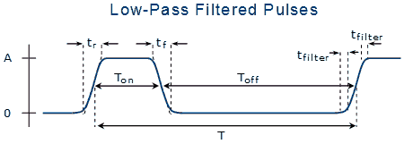
If the signal is passed through a single-pole low-pass filter with cut-off frequency Fh, the magnitudes of frequency components greater than Fh are given by,
These components are reduced by another 20 dB/decade, giving an overall fall-off as the cube of frequency, or 60 dB/decade.
Guidelines for reducing EMI
Understanding the sources of the upper harmonics in the spectra of digital signals we can implement several methods for reducing their intensities.
- Slew-rate limiting the digital transitions introduces a 20 dB/decade reduction in high frequency components.
- Low pass filtering the signals to round their edges introduces another 20 dB/decade reduction.
- It may sometimes be possible to choose fixed ON or OFF times for the waveform to null out specific harmonics.
See also →
- EMI reduction by optimizing the output voltage rise time and fall time in high frequency soft-switching converters2)


