Preventing PWM Noise
Proper grounding and correct instrument wiring prevent EMI/RFI and reduce noise radiation from high current PWM signals
High current, high frequency PWM signals are notorious for creating and radiating electromagnetic interference (EMI and RFI). Consequently, if you use PWM currents for controlling power devices, you should make your connections in a way that minimizes or limits the radiated noise. In general, single point grounding and using shielded twisted pair cable are essential to prevent EMI or mitigate PWM noise.
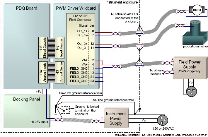
We'll examine these techniques in light of an example of an analytic instrument. Figure 1 shows connections of logic level inputs and field voltage outputs to the PWM board in a typical application:

In this case two devices are being controlled, a motor and a proportional control valve, using channels 1 and 3 respectively. The diagram shows field supply connections to VA+, which supplies channels 1-3-5-7. If channels 0-2-4-6 are also used, you can connect the same field supply to VB+, or you can use a different field supply for them by connecting it to VB+.
The diagram illustrates a few important design considerations you should follow in order to limit EMI radiation from the PWM signal lines. You might want to use these as a checklist in your instrument design. You can also examine the following if you are trying to diagnose an EMI noise problem or seeking to totally eliminate PWM generated noise:
- The field voltage input filter capacitors on the board draw a significant surge current when voltage is first applied, and if you supplement them with external capacitors1) the surge current will be even greater. Ideally, you should choose a field supply with a slew-rate-limited output that gracefully limits the output surge current.
- The diagram shows an external field supply used to power the PWM Driver Wildcard and potentially other external devices. Whether the field supply is placed inside or outside your enclosure, you must connect its negative return (often, but not necessarily, its ground wire) to the Docking Panel/PDQ Board ground as shown in the diagram above, and marked Field PS ground reference wire. The Field PS ground reference wire is essential – you must make this connection.
- To minimize EMI/RFI radiation, use shielded twisted pair cables for the field connections, including the field power and all device connections. For both the internal and external portions of the cable, the shield should be grounded to the enclosure at its point of entry/exit – and nowhere else. If you use enclosure-mounted connectors, reserve a connector pin for the shield and electrically connect it directly to the enclosure. In fact, for all cables that enter or pass through your enclosure, their shields should be grounded at the enclosure wall – but nowhere else. For both internal and external cables, the shield at the other end of the cable should be left unconnected. The single-point connection prevents current flow in the cable's shield, eliminating noise radiation from the shield. Usually, to mitigate an EMI or RFI problem, the first thing to look for are cables whose shields might inadvertently be carrying signal or drive current.
- It is not as important to use twisted pair for the Docking Panel or PDQ Board power cables as it is for the PWM power and output cables, but it is good practice for all internal power cables to also use twisted pair or shielded twisted pair cable. Ground the shield at the point of connection to the Docking Panel if you are using it, or to the PDQ Board if you are powering it directly with +5V. Keeping the power return path close to the power lines, by using twisted cable, greatly limits the radiated noise form power line current fluctuations.
- You can further mitigate noise by connecting the Docking Panel and PDQ Board assembly directly to your enclosure's ground. On the Docking Panel and PDQ Board, the digital ground signal is connected to the boards' frame grounds (the metalization of the mounting holes), so that mounting a stack of boards using aluminum standoffs to the enclosure grounds it to the enclosure. Even so, you should not assume good electrical contact by the standoffs, but instead make a separate, deliberate, reliable wired ground connection from the board to the enclosure.
- If you run AC mains power into the enclosure, directly connect the AC ground line to the enclosure, and run an additional failsafe wire from the AC ground line connector to the Docking Panel/PDQ Board ground as shown in the diagram.
- The diagram shows the ideal grounding at the point of the controller: a single bolt to the enclosure provides a star ground connection for the controller's frame and power return terminal, the AC line, the external field supply, and the shield of the controller's power cable.
The grounding techniques described here may be used to reduce EMI whatever the microcontroller or computer you are using, whether one of Mosaic's embedded controllers, a PIC, Arduino, or Raspberry Pi computer. These techniques should help limit PWM noise and eliminate radiated EMI.
