Measuring RTDs
Measuring RTDs with the 24/7 Wildcard
Unlike thermocouples, RTDs need no reference junction, but they do require sensitive instrumentation optimized for low resistance measurements. For example, a 100 Ω RTD with α = 0.00385 Ω/Ω/°C changes resistance only about 0.385 Ω for each 1°C increase in temperature. However, the wire leads connecting the RTD to the instrumentation might have a value of a few ohms, equivalent to an error of several degrees. Moreover, they too are temperature sensitive, so they can not be accounted for by just subtracting a fixed resistance.
In order to compensate for the resistance of the RTD’s wire leads, additional leads are often supplied. The two-wire RTD is suitable where lead lengths are very short, and a little error can be tolerated. Three-wire RTDs offer more refinement, with a separate voltage sensing lead that helps minimize the effects of lead resistance. The four-wire RTD configuration is usually used for best performance. We’ll examine the use of three- and four-wire RTDs.
Measuring 4-wire RTDs
Four-wire RTDs have two leads at each end of the RTD element. The are connected so that a current flows through one pair of leads, while the voltage drop is measured with the other pair. Lead resistance, shown as ΔR in Figure 1, does not affect accuracy, as insignificant current flows in the measurement side of the circuit as long as a high impedance voltmeter or A/D is used. Consequently, the voltage measured, VRTD, is the actual voltage drop across the RTD element.
If the RTD is placed in series with a reference resistor, for example a 10 KΩ at 0.1% resistor, the RTD resistance can be computed from the ratio of voltages across the RTD and reference resistor as,
RRTD = RREF * VRTD/ VREF
Most A/D converters provide an output scaled to the reference voltage given them, so if you use the VREF produced by the reference resistor as the A/D reference you can compute the RTD resistance as,
RRTD = RREF * A/D_Counts/ Full_Scale_Counts
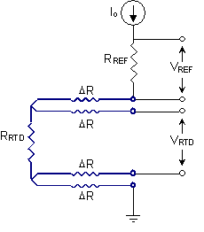
To minimize self-heating errors, the current through the RTD should be limited to less than 1mA. In the circuit of Figure 1 if the current is established by applying 2.5 volts, the current is less than 0.25 mA, and the voltage across the RTD element is only 0.025 volts. Because this voltage is small, a high-gain, low-noise analog input is required to measure the RTD voltage. The 24/7 Wildcard is ideal for this purpose – it provides programmable gain and filtering against power line noise.
Measuring 3-wire RTDs
Another common configuration for RTDs provides three wires instead of four. Figure 2 shows the required measurement circuit.
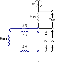
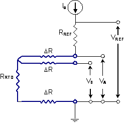
In the case of three-wire RTDs, two of the wires carry the measurement current, and consequently contribute voltage drops to the measured voltages, and one wire does not. In the circuit of Figure 2, VA measures the combined resistance of the RTD and two wires, while VB measures the resistance of the RTD and one wire. The three measurements, VA, VB, and VREF are combined to determine the RTD element resistance as,
RRTD = RREF * (2*VB- VA) / VREF
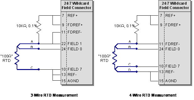
The above figure shows pin connections for connecting three- and four-wire RTDs to the 24/7 Wildcard. In each case, a 10 KΩ precision resistor is connected in series with the RTD between REF+ and REF-. The REF+/REF- pins provide a 2.5 volt precision voltage source to drive the circuit. The voltage across the 10 KΩ precision resistor is fed back to the field reference pins, and provides the reference voltage for the A/D – a little bit less than 2.5 volts. This automatically scales the A/D so that with a gain of unity a full scale reading corresponds to 10 KΩ.
On the left side, the three-wire RTD is measured twice using two pseudo-differential readings, once between channels 0 and 7, and again between channels 1 and 7. (Channel 7 is the pseudo-differential common.) On the right side, the four-wire RTD is measured only once, using one pseudo-differential reading, between channels 0 and 7. Alternately, you could connect it to use a fully differential measurement, for example between channels 0 and 1.
In each case, the RTD voltage is very small so you should configure the 24/7 Wildcard to amplify with a gain of 64. This gain value provides a full scale range of 10K/64 = 156.25 Ω so an RTD resistance up to 156.25 Ω, corresponding to a temperature of 147°C can be measured. If a greater temperature range is required the gain can be backed off to 32, allowing a full scale of 312.5 Ω or 596°C.
Measuring several 4-wire RTDs in series
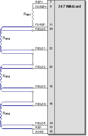
In some applications you may have several RTDs to measure. Figure 4 shows that several RTDs may be placed in series and fed with a single reference resistor. This is most easily done with four-wire RTDs, and with the A/D set to full differential mode. If a gain of 64 is used, the full scale range for each reading is still 156.25 Ω, corresponding to a temperature of 147°C.
Measuring several 3-wire RTDs in series
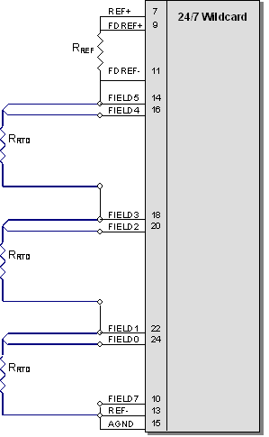
Three-wire RTDs can also be measured simultaneously by placing them in series and measuring the voltage at each node as shown in Figure 5. In this case, the voltage at each node along the resistive chain is read with respect to the voltage at the bottom of the chain using pseudo-differential mode. Note that in this configuration the voltage read at the top of the top RTD (FILED0 – FIELD7) is three times greater than that of one RTD alone, so the gain of the A/D should not be as great as when measuring a single RTD. The 24/7 A/D gain should be set to 16 instead of 64. After acquiring the voltage readings, the individual RTD resistances are found by doing several subtractions. If temperatures change between readings errors may be introduced, so using this methods places a limit on the maximum rate of temperature change that can still be measured accurately.
Connecting multiple RTDs robustly
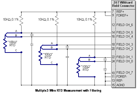
Figures 4 and 5 show the connection of multiple RTDs using only a single reference resistor. Those circuits are not robust with respect to the removal of an RTD. If any are unplugged, the others can not be measured. The following figure shows the connection of multiple RTDs so that if any are removed the remaining RTDs may still be measured.
A separate reference resistor is required for each RTD. In the prior measurement circuits the A/D's full scale reference voltage was taken from the voltage across the reference resistor alone, but in this case the full scale reference is taken from the series combination of reference resistor and RTD. That change requires that we compute the RTD resistance a little differently than before.
Each RTD is measured using single-ended measurement of two voltages, VA and VB, corresponding to the RTD leads labeled A and B in Figures 8 and 9.
Before, the RTD resistance was computed as,
RRTD = RREF * (2*VB- VA) / VREF
Now, because the reference voltage is taken from the series combination of reference resistor and RTD as shown in Figure 9, the resistance should be computed as,
RRTD = RREF * (2*VB- VA) / ( VREF- VA)
Lots of RTDs? No problem!
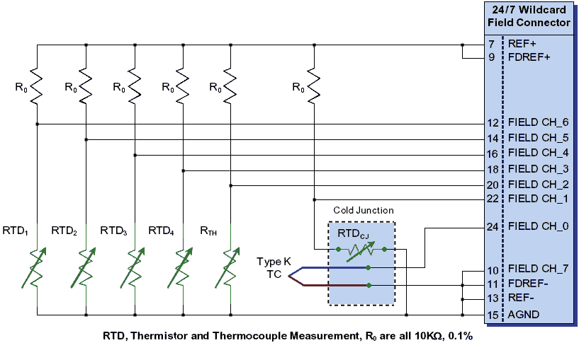
The Wildcard can measure up to seven channels, so if you have many RTDs to measure, or even thermistors and thermocouples, it's still easy. For example, the following diagram shows how to wire four RTDs, one thermistor, and a type K thermocouple with an additional RTD used for cold junction compensation of the thermocouple.

