Dynamically Program Voltage Regulators
Simple op-amp circuit for dynamically programming the output voltage
of otherwise fixed-voltage linear or switching regulators
There are many linear and switching regulator ICs that allow you to set their output voltage using a fixed resistor voltage divider, but few that are voltage programmable. Usually, you can set the output voltage to any fixed voltage greater than an internal reference voltage.
But you may need a power supply with the ability to vary the output to a value less than the reference voltage, or you may need a voltage programmable regulator, that is, to dynamically program the output voltage and vary it in response to a voltage command or a microcontroller's PWM output. Here we provide a simple op-amp circuit for a variable output voltage of an otherwise fixed voltage regulator. You can use this voltage programmed regulator circuit with typical DC-to-DC converters, converting them to variable output, PWM controlled, or voltage-controlled linear or switching regulators.
Fixed output voltage feedback networks
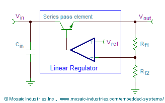
Figure 1 shows a typical circuit configuration for a fixed output voltage linear regulator.

The regulator contains a controller with a feedback voltage amplifier that compares an external voltage, derived from the regulator's output voltage through a resistive divider network, to a fixed internal voltage reference. The output of the error amplifier drives a series pass element, or power stage, which delivers current to the output. By setting the external resistors, Rf1 and Rf2, you can set the regulator's output voltage to any voltage greater or equal to the internal reference.
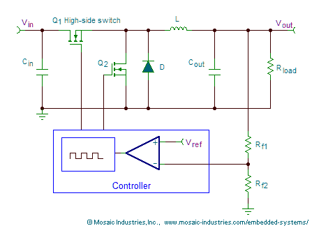
Figure 2 shows a typical circuit for a step-down, or buck, switching regulator. It is controlled similarly to the linear regulator, with a similar error amplifier, except in this case the series pass element is rapidly switched ON and OFF with a PWM or pulse frequency modulation scheme, and the resulting power waveform filtered to produce a constant DC voltage output.

For either the linear or switching regulator configuration, the output voltage is wholly determined by the feedback divider network, and is given by,
Dynamically programmable feedback for variable output voltages
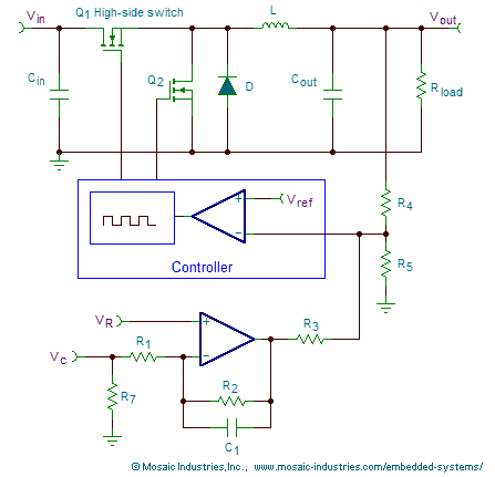
If you need a variable voltage power supply with dynamically programmed output voltage you can use an active feedback network that incorporates an op-amp. The following circuit shows the circuit design for use with a switching regulator; you can use the same circuit addition for linear regulators too.

An input control voltage, Vc, is inverted by the op-amp and added to the feedback node of the voltage regulator. The regulator adjusts its output to servo that feedback input to the regulator's internal voltage reference. When the control voltage is low, the op-amp output is driven high, and the it pulls the regulator's feedback pin high. To compensate for that, and keep the regulator within its operating range, the regulator drives its output low. Consequently, the regulator's output can be regulated at a lower voltage output level than its internal reference voltage. When the control voltage is high, the op-amp output goes toward ground, pulling the feedback pin low. To compensate for that, and keep the feedback voltage constant, the regulator must increase its output voltage. The overall effect is to linearly control the regulator output voltage with the control voltage.
Equation 2 provides the regulator output voltage, Vout, as a function of the control voltage, Vc, the regulator's internal reference voltage, Vref, an additional reference voltage applied to the op-amp, VR, and the resistor values.
As you can see, the output voltage varies linearly with the control voltage, with a positive slope (or gain) given by resistance ratios. There is also an intercept, or zero offset, that depends on the relative magnitudes of the internal reference voltage and the additional reference voltage. Resistance values can be chosen to provide the desired gain and intercept.
The following table provides exemplar values for a voltage controlled power supply using the LM2678 regulator with a 28 V input acting as a step down regulator with an output voltage of 0 V to 24 V.
| Parameter | Value | Notes |
|---|---|---|
| Internal reference | 1.21 V | The internal reference of the LM2678 |
| VR | 2.5 V | Applied to the op-amp positive input |
| R1, R2, R3 | 10 KΩ | Chosen to make the op-amp a unity gain inverter. |
| R4 | 60 KΩ | Chosen to set the gain of the circuit. |
| R5 | 4.67 KΩ | Created by two resistors in parallel, 4.7 KΩ and 866 KΩ |
| R7 | 4.7 KΩ | Assures positive shutoff when the input is disconnected |
Using the values of the table above, the output voltage as a function of the control voltage becomes,
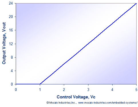
Of course, the output voltage can not go negative, so it is zero for a control voltage of 0 to 1 V, providing assurance of positive shut-off when the control voltage is insubstantial. For Vc from 1 V to 5 V, the output voltage increases with a gain of 6 V/V, to 24 V when the control voltage is 5 V. The following graph shows the transfer function:

Choosing component values for a voltage controlled power supply
Component values are chosen by considering the desired ranges for the control and output voltages, the op-amp's output voltage range, and the gain and zero offset of Equation 2. We'll consider a design example for a step-down switching supply using the LM2678 regulator IC, with the following design objectives:
- The output voltage should be controlled over the range of 0-24 V. The supply of the LM2678 should be 28 V or greater to allow that output.
- The control voltage should range from 0-5 V.
- The internal reference of the LM2678 is 1.21 V. Some regulators provide a reference output, but the LM2678 does not. So, we may use any other convenient reference for the VR input to the circuit.
- We would like to assure complete turn-off of the output, despite any inaccuracy in the regulator's internal reference voltage or small variations in component values, so we'll design the circuit to put out zero volts for control voltages less than 1 V.
Given these constraints, we continue the design as follows:
- First, we'll choose a rail-to-rail op-amp such as the MCP6004, and power it from a 5 V source. We can divide the 5 V source with a resistive divider to provide a 2.5 V reference to the op-amp's positive input, as VR.
- We'll choose R1 and R2 to be the same, and equal to 10 KΩ. The op-amp then becomes a unity gain inverter, converting the VC range of 0-5 V to 5-0 V.
- We want the output voltage to swing from 0 to 24 V as the op-amp output swings from 1 to 5 V. Consequently, the gain needed is 6 V/V. The gain is given by R4/R3 (provided R2=R1), so we'll try R4 = 60 KΩ and R3 = 10 KΩ.
- Having established the gain, we now want the output to be shifted so that it is just 0 V when the input is 1 V. So we use Equation 2 to calculate the value or R5 needed. We find a value of 4.675 KΩ, which we can attain by using two resistors in parallel, one 4.7 KΩ resistor and one 866 KΩ resistor.
- Finally, R7 in Figure 3 is chosen to assure that the output voltage remains zero even if the control voltage line is disconnected. Any resistance less than 6.66 KΩ will work, for sufficient noise margin we choose 4.7 KΩ.
A convenient way to do the calculations is to use a spreadsheet. This Excel file provides the equation and a table of results. Using it, you can change the desired input and output ranges and re-optimize the component values.
PWM programmable linear or switching regulators
The circuit of Figure 3 shows a feedback capacitor to be used when driving the circuit with a PWM waveform rather than a DC control voltage. The capacitor provides an integrating function so that the op-amp responds to the average value of control voltage. With it, you can provide a PWM waveform and the op-amp will average it to its DC value (that is, its duty cycle times its amplitude). There is no harm in using the capacitor even when a DC voltage is used as a control voltage, except that the response time of the circuit is slowed to the RC time of the op-amp's feedback network.
When driving the circuit with a PWM waveform, you should use a PWM frequency great enough that its period is one tenth or less of the op-amp's RC time constant, that is,
Dynamic response to changes in control voltage
This op-amp circuit offers a simple solution for dynamically programming the output of a DC-to-DC converter. The response time for the output to change after a change in control voltage is limited by several factors:
- The response time is limited by the inherent bandwidth of the converter control loop. In the case of a switching regulator, that control loop's bandwidth is dominated by the LC filter time. For stability of step-down converters, the LC cut-off frequency must be set to a frequency less than the switching frequency divided by 2*PI. The converter's internal error amplifier is usually internally compensated to limit its bandwidth to that value. In many cases the control loop bandwidth is further limited by choosing a significantly lower LC cut-off frequency so as to minimize output ripple. For a converter like the LM2678, with a 260 KHz switching frequency, the LC bandwidth is limited to 40 KHz, and in practical designs it is often in the range of 1 KHz to 25 KHz.
- A second limitation is the slew rate of the converter for large voltage changes. The slew rate for charging output capacitance is determined by the current capability of the converter's series pass element, while the slew rate for the discharge of the output capacitance is determined by the output load current.
- Finally, the op-amp response time may be limiting if its slew rate is too slow or its bandwidth too small. In particular, if you provide a feedback capacitor, C1, to filter PWM input waveforms, the R2C1 integration time will limit the overall response time to changes in control voltage.
Switching regulator stability
The circuit works well with linear regulators and most switching regulators. However, some step-down switching regulators can not be driven all the way down to zero duty cycle; they are limited by a minimum ON time for their high-side switch. Despite that, some of those regulators will skip pulses or lower their frequency to gracefully dial down to nearly zero output, but others may operate only at a fixed frequency. For those, you may need to take special measures to assure positive shut-off.
Further, some step-down switchers will become less stable or exhibit greater output ripple voltage at low output voltages. You'll need to consult their data sheets to fully understand their behavior at the limits of their output excursion.
See also:

