Precision Measurement Without Ground Offsets
A simple opamp circuit removes ground loop offsets and common mode noise from precision measurements
The problem: ground loops!
Probably the most common source of error in any analog to digital measurement system is improper grounding. To accurately measure an analog signal, the producer of the signal, that is the sensor, and the measuring device, usually an A/D converter in a microcomputer system, must share a common ground reference. In practice, that is often difficult, and the two ground references may differ in voltage by millivolts to volts.
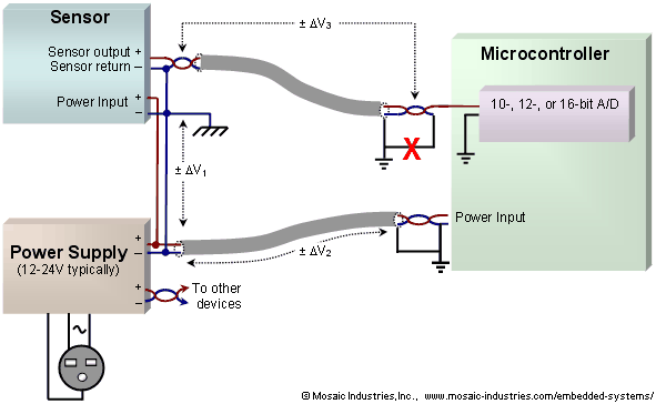
Unless they are fully isolated, analog output sensors must refer their output voltages to a ground reference. Unfortunately, if the analog sensor requires power its ground is usually connected to its power supply's ground, which in turn may eventually be connected to an earth ground. However, power supply current in the ground wires produces small voltage drops that separate the sensor's ground from the earth ground. Likewise, the microcomputer's power supply may eventually be connected to an earth ground, but again its power supply current flowing through its supply wires create another voltage drop. The differing grounds are illustrated in the following figure:

Referring to Figure 1, the power supply currents create ground differentials of ±ΔV1 and ±ΔV2. These error voltages are added to the sensor output, and result in errors in measurement. Because the supply currents may contain a great deal of digital noise, the error voltages are not merely small DC offsets, but usually contain an appreciable noise voltage.
Attempts to better tie together the grounds of the sensor and measurement system usually don't help. Consider what happens if the sensor return wire is tied to the measurement system ground – the connection with the big red X in the above diagram. That merely provides another path for the microcomputer system's power current to flow through the sensor's return wire, producing yet another offset voltage, ±ΔV3.
Mitigating ground loop offsets
Ideally, you would reduce noise and ensure measurement accuracy by eliminating ground loops. When at least one device, such as the sensor, can be isolated, then the offending ground path is open, no current flows, and the noise or inaccuracy is eliminated. Unfortunately, that is often not possible – for cost or availability reasons you are often stuck using non-isolated sensors.
There are two other solutions. The first measurement technique is to use a differential input A/D converter, or to simulate a differential A/D by using two A/D channels and doing the subtraction in software. This technique often works well when the ground offset voltage is a small DC offset. But if the offset voltage is noisy, it's difficult to compensate by performing two measurements separated in time – the offset voltage changes between the two measurements. Even differential input A/D converters usually measure the two inputs at slightly different times. Further, if the offset is negative it usually can not be measured by A/D converters which usually have only positive input ranges.
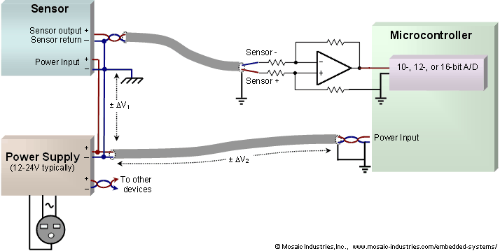
The second measurement technique is to use a differential amplifier or instrumentation amplifier to remove the offset, as shown in the the following diagram:

In this case, the differential amplifier looks at the sensor signal and its return wire, finds the difference between the two, and produces an output that is referred to the ground of the measurement system. If the differential amplifier has sufficient bandwidth, it removes the AC component of the offset voltage too, including components of power line ripple and digital noise.
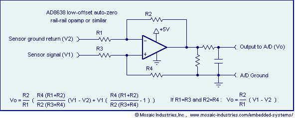
Lets take a closer look at the circuit for the differential amplifier:

The amplifier uses four resistors that must be matched. In particular, if R1=R3 and R2=R4, the amplifier rejects the offset voltage and delivers the amplified signal to its output. The resistors don't need to be perfect, but commonly available 0.1% resistors can be used. With matching of the order of 0.1%, 99.9% of the offset signal is removed (that is, the noise is suppressed by 60 dB). As the offset is usually small anyhow, from a practical standpoint the rejection is very good. The amplifier does introduce a small full scale (or gain) error.
The differential amplifier effectively removes negative ground offsets as well as positive ground offsets. Depending on the measurement range you need, you may be able to use a rail-to-rail op-amp as shown in the circuit. Be careful though – rail-to-rail op-amps do not really pull their outputs fully to the supply rails, but only to within 5-10 millivolts of the rails at best, and often only to within 100 mV. You may be able to add a resistor to ground (or to a negative voltage if you have one available) to enable the output to go fully to ground, or you may need to provide a negative supply to the op-amp itself.
About using shielded cables
The above diagrams show the use of shielded twisted wire cable for the sensor signal and power supplies. If shielded wires are used, the shielding must be grounded at one end of the cable only, usually the measurement system end. If grounded at both ends, ground current will flow through the shield and inductively induce noise into the signals wires, as well as create further ground loop offsets.
Safely connecting to transformerless-supply circuits
A popular Microchip Application Note, AN954 Transformerless Power Supplies: Resistive and Capacitive, shows how to build transformerless, non-line-isolated power supplies for low power electronics. Because these supplies are not isolated from the AC power line they generally can not be connected to anything else. In particular, you can not connect an oscilloscope to measure their internal signals, and you can not connect an output signal from them to other devices. Similarly, Apex Technologies Application Note 35 shows non-line-isolated power supplies that can not be connected safely to other devices.
In the case of the Microchip Application Note, the circuits described provide an internal ground reference positioned with a high AC voltage with respect to the AC neutral line. Any connection of it to an earth ground is likely to result in fireworks. The Apex Application Note describes circuitry whose internal ground is connected to the AC neutral line, but any external connection to that would violate local electrical codes and could present a significant ground-loop current hazard if connected to external equipment that is earth grounded. Without connecting the two different grounds there is a high noise between them, noise that may include high voltage AC, but also includes the high frequency noise generated by any other equipment on the AC line. So a hazard is created if the grounds are connected, and high voltage offsets and noise prevent measurement if the grounds are not connected.
The solution to this dilemma is to connect external devices using the above differential amplifier, configured for unity gain operation:
- First, the non-isolated power supply should always be configured to use the AC line neutral for its internal ground. The circuits of AN954 should be changed to do that. It's beyond my ken as to why Microchip published the application note showing the circuits as they do! By any measure, they are dangerous designs.
- Signals may be monitored by using the above circuit, using resistors R1-R4 of values of at least 100K. Connect the R3 input to the "ground" of the non-isolated device, and the R1 input to the signal of the non-isolated device to be monitored or measured. Then the circuit's output is referred to the ground of the output device, for example, an oscilloscope.
- You do need to assure that the common-mode voltages presented to the op-amp stay with its input range. That may require:
that you attenuate the input signals with resistor dividers to bring them into the op-amp's common mode range,
that you use a dual supply for the op-amp,
that you decrease its gain by decreasing the values of R2 nad R4,
that you use large input common mode op-amps made for this purpose, or,
some combination of the above.
See also → Precision Measurement without Ground Offsets
