Cell Constant of Interdigitated Electrodes
The cell constant of microfabricated planar interdigitated electrodes used in electrolyte conductivity sensors
is found by solving Laplace's equation for the electric fields using a relaxation method.
Electrolyte conductivity sensors are widely used for measuring the conductivity of both aqueous and non-aqueous solutions, as well as the basis of various chemical sensors. The sensors are very simple; they comprise a pair of electrodes exposed to the electrolyte solution.
Conductivity sensors are characterized by a cell constant – a geometry dependent parameter that relates the conductance (or resistance) measured by the cell to the solution's conductivity (or bulk resistivity), as,
where,
K is the cell constant, in cm-1, and,
σ is the solution conductivity, as S/cm or µS-cm-1.
Conductivity sensors are fabricated using a variety of electrode geometries. In the past the use of parallel planar electrodes made determination of the sensor's cell constant an easy computation. In that case the cell constant is given by the ratio of electrode separation to electrode area:
This equation holds well for large electrode areas and small separation. In that case, most of the electrode current flows directly between the electrodes, and the small current in the fringing field can be neglected.
But now it's possible to manufacture miniature electrolyte conductivity sensors using microfabrication techniques. These sensors usually use planar-interdigitated electrodes, around and between which the solution conductance is measured. While conductivity cells using these electrodes may be calibrated using standard solutions, diagnosis and verification of cell function still requires an a priori estimation of their theoretical cell constant. But that's difficult because in this case all the electrode current flows through the fringing field.
In the following derivation we develop and present an expression for the cell constant for planar-interdigitated electrodes, considering the number of electrode fingers, their width, and the space between adjacent fingers. We compare our results to other theoretical models.
The method developed here provided a simple computational means of determining cell constant, and showed that over a wide range of electrode spacing the cell constant may be accurately approximated as an inverse cube of the ratio of electrode spacing to electrode width, Eqn. 5 below.1)
Finite element relaxation solution to Poisson's equation
The cell constant is found by determining the current flow through a plane separating the electrodes. The current is assumed to be ohmic, that is, directly proportional to the voltage gradient across the plane. Using a finite element method the plane is divided into small cells, and the current flow through the cells summed.
The voltage gradient across each cell of the plane is found by solving Poisson's equation for the potential distribution in the medium surrounding the electrodes. In principle the potential field may be analytically determined from Poisson's equation. In practice, for arbitrary electrode geometries it is just too complicated to solve Poisson's equation analytically. Instead, the potential field may be found by solving Poisson's equation iteratively. In this work we solve Laplace's equation (the limiting case of Poisson's equation in which there is a zero charge distribution throughout the medium) using a relaxation method.
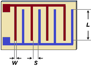
We'll consider the following sensor geometry comprising an interdigitated electrode pair in which there are N fingers of length L and N-1 gaps between fingers:
The width of each finger is W and the gap separation is S. We assume that L » S so that we can neglect end effects at the ends of the electrodes. We'll assume that the thickness of the electrodes is negligible in comparison to the separation, and that if there are any insulating layers placed above the electrodes they are thin enough to be neglected. With these assumptions, all the electric field above the plane of the sensor lies within the electrolyte being sensed.
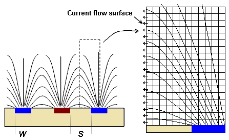
Consider the electric field distribution surrounding the electrodes:
We model the area of the dotted rectangle and solve the two-dimensional Laplace equation using a relaxation method constrained by the obvious boundary conditions. We assume the electrodes provide equipotential surfaces. The vertical plane bisecting the gap is an equipotential plane with a voltage value equal to the average of the values of the opposing electrodes. The top edge of the modeled rectangle is also assumed to be an equipotential surface at the same value.
All current flows through that bisecting plane, and because the electric field is perpendicular to that plane at all points the current flow is also perpendicular to the bisecting plane, and proportional to the voltage gradient at each point. The voltage gradient across the plane is strongest near the electrodes, and decays quickly with distance from the plane; consequently, conductance contributions are greatest nearer the electrodes. The cell constant is found by summing conductance contributions to find an overall, bulk conductance. Computationally, that is found by summing all the voltage gradients across the bisecting plane.
The width of the modeled area is (W+S)/2 and the height is 3.33 times the width. We divide the area into 300 elements across (each element is of width (W+S)/600) and 1000 elements high. Using Laplace's equation we then iteratively solve for the potential (voltage) at each point for various ratios of S/W. We carry out the relaxation until the voltage value of each cell changes less than one part in 108. Once the iterate is stable, the voltages between the cells separated by the bisecting plane are summed to find the overall conductance. That is, after each solution for a specific value of S/W we sum the differences in voltage, ΔV, across the surface marked in the drawing (the leftmost column of cells in the finite element grid) to determine the cell constant. Twice the inverse of that sum provides the normalized cell constant, as,
The value of K thus found is displayed in the following graphs as the "simulation results". This computation method provided us with values of K as a function of the ratio S/W.
In plotting these K values as a function of S/W we noticed that they conform well to a power law function. In particular, we found that over the practical range of 0.1 < S/W < 10 this data is well represented by a simple power law relationship, as,
Over this range, we find the data (that is, K generated by the iterative solution to Poisson's equation) is fit to within ±1.7% by this simple power law. This 1/3 power law is not surprising, as the intensity of an electrical dipole field falls off with the cube of distance. Consequently, we find that over two orders in S/W the cell constant is given by,
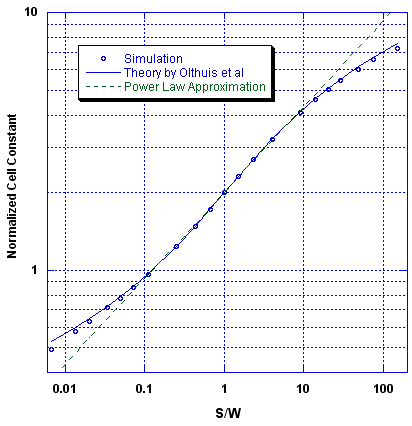
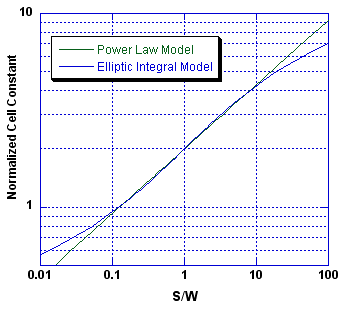
The following graph shows the correspondence between the computer simulated cell constants found, a theory (described in the next section), and the simple power law approximation.
The granulation of our simulation introduces some error into the results. In the mid-range (0.1 < S/W < 10) those errors are less than 1%, but grow to about 5% for extreme values of S/W for which there are only a few cells representing either the electrode width or separation. We find that the simulation results agree with the predictions of the Olthuis theory (described below) to within that error.
Comparison with other theoretical models
Other researchers have produced theoretical determinations of the cell constant for interdigitated electrodes. In particular, Olthuis et al2) found an analytical solution for the potential distribution by using a method of conformal mapping to transform the field geometry into one more easily solved analytically in the new coordinate system. It's a great mathematical trick, and I recommend reading their paper even for that alone.
However, their analytical solution is a bit messy, involving elliptic integrals, which are themselves not computable in closed form. They find that the cell constant is given by the following equation:
where F is a complete elliptic integral function of the parameter x, where x is given by
for electrode arrays with only two fingers (N = 2), and by,
for electrode arrays with more than two fingers. The function, F(x), is the complete elliptic integral of the first kind, as,
where the integration is taken from t = 0 to t = 1.
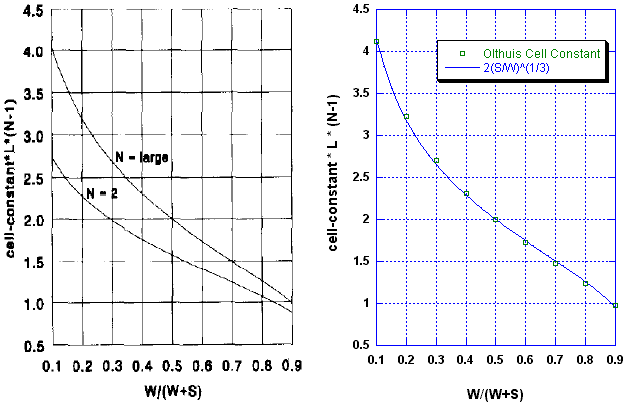
Despite the complexity of the analytical solution, it can be represented as a simple graph, which I reproduce here from their paper, as the graph on the left:
Olthuis et al also compared the theoretical model to experimentally determined cell constants for a series of differently shaped interdigitated electrodes. Their fabricated cells showed systematically greater conductance than that theoretically calculated. Their explanation for the systematic discrepancy was the presence of fringing effects owing to a thin insulating layer they had placed over the electrodes, causing the electric field to diverge at the insulator-solution interface. That divergence inflated the apparent electrode width, W, increasing the conductance.
The above side-by-side graphs compare our model to the Olthuis theoretical model. We find that the simple formula,
provides a good approximation to the much more complex and difficult-to-compute theoretical equations (Equations 6 to 9) over the range of the comparison, that is, for 0.1 < S/W < 10.
Over this range, the simple power law model fits the theoretical model to within ±2%, as shown in the following figure:
Over the range of realistic electrode geometry, that is for 0.1 < S/W < 10, the inaccuracies of the power law approximation are generally much smaller than the inaccuracies found by Olthuis et al caused by thin insulating layers over the electrodes. Further, they are expected to be small in comparison to the inaccuracy of the assumption that L » S, that is, the errors caused by neglecting end effects at the ends of the finite length electrodes.
Consequently the power law equation provides a computationally simple and accurate approximation for assessing the expected cell constant of realistic electrode arrays.
Over a broader range, that is, for S/W « 0.1 or S/W » 10, the power law no longer fits the theoretical model well, as shown in the following figure:
Despite the lack of fit at extreme values of S/W, the simpler power law does fit well over two orders of magnitude. Values of S/W around unity are of the most interest as they represent practical implementations of sensors. Microminiaturization efforts aimed at fabricating the greatest electrode densities require that electrode width and spacing be comparable.
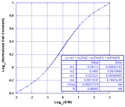
As the Olthuis model is difficult to compute the power law equation may be used instead for the range 0.1 < S/W < 10. If greater accuracy is needed or for a greater range of S/W, you may use the following polynomial approximation of the Olthuis solution, which is applicable over the range of 0.001 < S/W < 1000:
K = k /(L(N-1))
This approximation fits the Olthuis model to within 0.6% over the 0.1 < S/W < 10 interval, and it fits to within 1.3% over the full range of 0.001 < S/W < 1000, as shown in the following figure.
Conclusions
A simple expression for the cell constant of interdigitated planar electrodes was derived from computer simulations of the fringing electric field surrounding the electrodes. The field magnitude was found by iterative solution of the Poisson/Laplace equation using a relaxation method. We find the data to fit an inverse cube law very well. The found expression is in accordance with other theoretical models while providing a simpler and more easily computed value for practical electrode dimensions.
While computationally intensive and somewhat slow, the method we used, iterative solution of Laplace's equation, is applicable to arbitrary electrode geometries for which an analytical treatment is not feasible.
But to find the cell constant of interdigitated electrode arrays you needn't use the iterative method. Instead, the power law equation, Eqn. 5 above, is applicable to all multi-element interdigitated electrode arrays with parallel electrodes whose lengths are substantially greater than their widths or separations. You can use the power law equation as a computationally simple and accurate approximation for the cell constant of realistic electrode arrays.
See these pages for more instrumentation information about the Conductivity Sensing Wildcard →

