Customizing Your Handheld Instrument
Your Handheld comes with 17 I/O signals including timer controlled digital I/O, 8 lines of 8-bit A/D, and two serial ports. You can further customize its I/O by:
- Adding WildCards for virtually any kind of I/O;
- Routing any I/O signals to the Handheld’s DB-25 connector;
- Filtering and/or protecting any of the I/O; and,
- Adding custom circuitry.
Using the Personality Board to Customize I/O
The Handheld’s Personality Board allows you to place your own custom circuitry into the Handheld, to mount WildCards for custom-off-the-shelf I/O, to route any of the Handheld’s signals to its DB-25 connector, or to filter, protect, or condition any of its I/O signals.
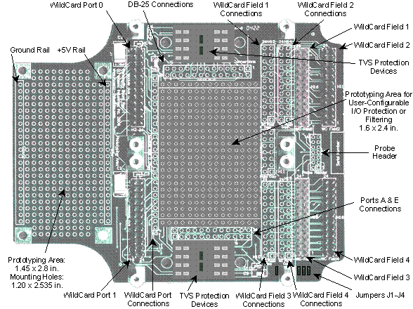
Figure 13-1 shows the Personality Board. There are two prototyping areas you can use to mount custom sensors, actuators or to include your custom circuitry. On the left is a sea-of-holes area 1.45" x 2.8" in size, and in the center is another area 1.6" x 2.4", each with holes positioned on 0.1" centers. On the right are field connections for up to four WildCards. Each of the field connectors for the WildCards is mirrored with a sea of holes to provide access to any of the field signals. Corresponding hole patterns for the DB-25 connector and the Processor Board’s native I/O are provided so that you may point-to-point wire from any I/O signal to the DB-25 connector.
The sea-of-holes prototyping areas provide space for mounting custom sensors, actuators, amplifiers, or protection circuitry. You can point-to-point wire from your custom components to other sea-of-holes images for connecting to the Wildcards, to the processor ports A and E, to the serial ports, or to the DB-25 connector. There are transient voltage protectors premounted on the board so you can easily protect up to eight I/O lines that you run out of the instrument.
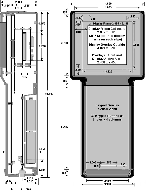
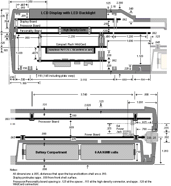
Figure 13-2 and Figure 13-3 show the internal and external dimensions of the Handheld. There is considerable volume between the Personality Board and the Handheld’s back shell. This volume is roughly in the shape of two adjacent cubes, one of approximately 17.7 in3 (4.0" x 3.4" x 1.3") available for mounting Wildcards or your custom hardware, and another of 5 in3 (appx. 1.5" x 2.8" x 1.2") over the prototyping area. Even if you fill the Handheld with four Wildcards, there is still the sizeable prototyping area available for your custom devices.
Figure 13-1 The Personality Board showing two sea-of-holes prototyping areas.
Table 13-1 H7: Field Connection Area (Ports A&E)
| Signal | Pins | Signal | |
|---|---|---|---|
| GND | – 1 | 2 – | +5V |
| AGND | – 3 | 4 – | V+RAW |
| /TxD1 (/TxD2) | – 5 | 6 – | /RxD1 (/RxD2) |
| XCVR- (/TxD2) | – 7 | 8 – | XCVR+ (/RxD2) |
| PA7 | – 9 | 10 – | PA6 |
| PA5 | – 11 | 12 – | PA4 (TxD2) |
| (RxD2) PA3 | – 13 | 14 – | PA2 |
| PA1 | – 15 | 16 – | PA0 |
| PE7/AD7 | – 17 | 18 – | PE6/AD6 |
| PE5/AD5 | – 19 | 20 – | PE4/AD4 |
| PE3/AD3 | – 21 | 22 – | PE2/AD2 |
| PE1/AD1 | – 23 | 24 – | PE0/AD0 |
| Note: Signals in parentheses indicate options configured using jumpers on the handheld motherboard. | |||
Table 13-2 H1 & H2: Wildcard Port Headers
| Signal | Pins | Signal | |
|---|---|---|---|
| GND | – 1 | 2 – | +5V |
| /IRQ | – 3 | 4 – | V+Raw |
| PG1/XMIT- | – 5 | 6 – | PG0/XMIT+ |
| MOSI/XCV- | – 7 | 8 – | MISO/XCV+ |
| /RESET | – 9 | 10 – | SCK |
| /MOD.CS | – 11 | 12 – | 16 MHz |
| E | – 13 | 14 – | R/W |
| /OE | – 15 | 16 – | /WE |
| AD7 | – 17 | 18 – | AD6 |
| AD5 | – 19 | 20 – | AD4 |
| AD3 | – 21 | 22 – | AD2 |
| AD1 | – 23 | 24 – | AD0 |
Routing I/O Into the Instrument
Figure 13-1 shows that the Personality Board includes a hole pattern corresponding to the DB-25 signals, labled "DB-25 Connections". All the DB-25 lines are routed for you from the connector to these holes with a one-to-one correspondence of pin numbers. You may point-to-point wire on the Personality Board from any of the WildCard field headers, the Port A and E Connections, or your custom circuitry to these holes.
In addition, there are four pairs of Wildcard field header interfaces and copies. The WC Field headers are intended to connect with ribbon cables to the field headers of any installed Wildcards, and the WC Field Copy holes are intended to allow those signals to be routed as needed for your application in the prototyping area.
Table 13-1 shows the pinout of the field connection area H7 on the Personality Board. This set of holes provides access to the HC11 processor digital I/O PORTA and analog/digital I/O PORTE. To use PORTE for analog data acquisition, see Data Acquisition Using Analog to Digital Conversion
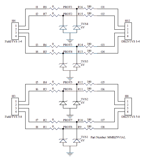
Finally, there are two areas for building series protection circuits on the Personality Board, behind both the H6 DB25 connection area and the H7 field connection area. Figure 13-2 shows the intended usage of these areas. A series protection circuit may be installed in any non-power signal path between a node on the 4-hole Field/TVS connections H3 and H4, and the 4-pin DB25/TVS connections H8 and H12. Figure 13-2 shows protection circuits configured for input signals. For outputs from the Handheld, reverse the 0 Ω and 100 Ω resistors.

Figure 13-2 The two series protection circuit areas.
Mounting Additional Components
Figure 13-3 The Handheld’s external dimensions (in inches). Two optional Wildcards are shown stacked on the Personality Board.
Figure 13-4 The Handheld’s internal dimensions (in inches), showing the dimensions of two optional Wildcards stacked on the Personality Board. One Wildcard is a Compact Flash card interface.


