Board Dimensions and Mounting
When designing your new instruments you'll need to keep in mind the physical dimensions of the electronic boards.
Stacking, customizable boards for electronic instrument development
Microcontroller based instrument design and development requires some flexibility in choosing controller and I-O boards. Mosaic's single board computers and Wildcard I/O boards may be conveniently stacked to provide customizable I/O. The 2.5" x 4" PDQ Board can host two stacks of 2" x 2.5" Wildcards, each containing up to four I/O boards. Each Wildcard has a go-though header for the Wildcard bus, that passes the bus up to the next Wildcard. Wildcards may be mounted using standard 1/2" standoffs in corner holes.
Physical dimensions of the PDQ Board instrument controller
The following is a top view of the layout of the PDQ Board.
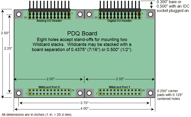
The board is an FR4 0.065" thick PCB with a 2.5 x 4 inches footprint, with standard 0.1" spacing 24-pin (2x12) right angle headers providing connection to the board's analog and digital I/O. These two field headers accommodate standard IDC ribbon cable sockets. See below for mechanical details of the connector placement.
The tallest components on the bottom of the board are the two 24-pin Wildcard bus sockets at H3 and H7. They rise 0.340 in. above the surface of the board, as shown in Connector Placement below. Similarly, the tallest components on the top of the board are the pins of those same sockets; they rise 0.335 in. from the surface of the board.
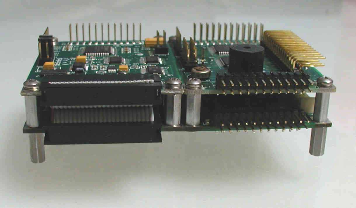
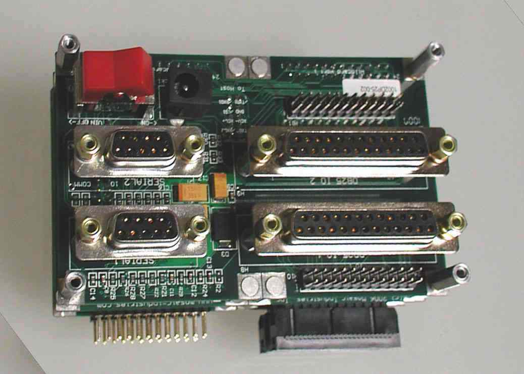
The following photo shows a bottom view of the PDQ Board with a ribbon cable connector attached to the digital I/O field header.
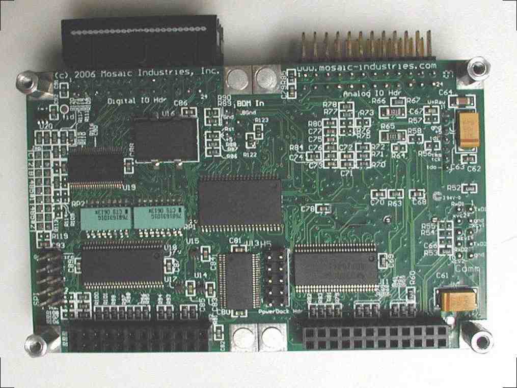
The eight corner holes are used both for mounting and to accommodate Wildcards. A single Wildcard may be mounted in either position, connecting to Wildcard Bus 0 or Wildcard Bus 1 on the figure.
Physical dimensions of Wildcard I/O boards
The Wildcards use a similar layout, except that they are 1/2 the size as the PDQ Board. On one side they have a Wildcard go-through header, and on the other a single field header. The following top and side views of a typical Wildcard shows the dimensions common to all Wildcards:
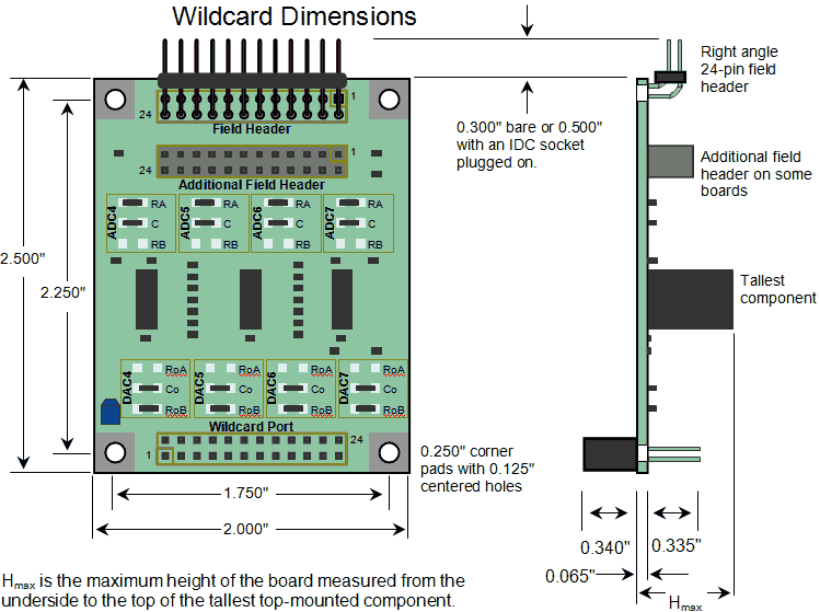
Both the PDQ Board and the Wildcards have similar cross-sectional views – the mounting holes line up so that Wildcards may be stacked on top of the PDQ Board. The side view in the above diagram shows the dimensions of the stacking-go-through Wildcard bus connector and the right angle field header connectors.
Aside from the edge connectors there are other headers on the boards, some with configuration jumpers. Those jumpers add a little height, making the maximum height (Hmax on the figure) at least 0.365". On the PDQ Board, no component rises higher than the edge connectors, so the maximum height is given by the height of the Wildcard headers.
Only small passive devices are mounted on the bottom of the Wildcards, but some Wildcards have larger components on their top side.
Connector placement
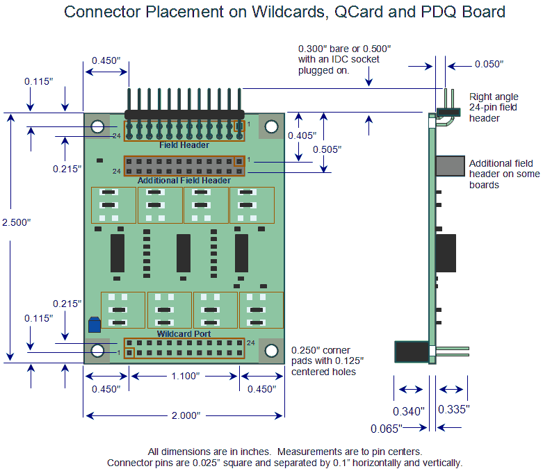
Mosaic's single board computers and I/O boards simplify instrument design by using standard dual-row headers for stacking and field connections. Generally, 24-line IDC connectors and ribbon cable may be connected to the boards. The following figure shows the precise locations of the connectors on the boards, with dimensions drawn to the center of the pins.
Height and weight of Mosaic's microcontroller and I/O boards
The following table provides the weights and maximum height of the top- and bottom-side components for the PDQ Board, QCard, and each Wildcard. Top height is the distance from the top surface of the board to the top of the highest projection (including jumper caps), and bottom height is the distance from the bottom surface of the board to the bottom of the lowest projection. You may need to reserve additional space above or below a board for plugging connectors onto headers.
| Part Number | Description | Weight (grams) | Bottom Height (inches) | Top Height (inches) |
|---|---|---|---|---|
| PDQB | PDQ Board | 48 | 0.340 | 0.335 |
| QCC | QCard Controller | 31 | 0.340 | 0.365 |
| DP | Docking Panel | 112 | 1.0 1) | 0.400 |
| DP-slim | Docking Panel - Slim | 50 | 1.0 2) | 0.365 |
| W-ACM | AC Solid State Relay Wildcard | 55 | 0.340 | 1.100 3) |
| W-AIM | Analog I/O Wildcard | 18 | 0.340 | 0.365 |
| W-CFM | Compact Flash Wildcard | 18 | 0.340 | 0.365 |
| W-COND | Conductivity Sensing Wildcard with isolation capacitors | 43 | 0.475 | 0.875 |
| W-COND-x | Conductivity Sensing Wildcard without isolation capacitors | 21 | 0.340 | 0.365 |
| W-DA24/7 | 24/7 Data Acquisition Wildcard | 19 | 0.340 | 0.365 |
| W-DCM | DC Solid State Relay Wildcard | 34 | 0.340 | 0.575 4) |
| W-DIM | Digital I/O Wildcard | 23 | 0.340 | 0.365 |
| W-ETHx | Ethersmart Wildcard | 25 | 0.340 | 0.550 5) |
| W-GPS | GPS Wildcard | 26 | 0.340 | 0.365 |
| W-IOF | I/O Filter Wildcard | 16 | 0.340 | 0.365 |
| W-KPD | Keypad/Display Wildcard | 26 | 0.340 | 0.380 |
| W-LCVR | LCVR Driver Wildcard | 20 | 0.340 | 0.415 |
| W-Proto | Prototyping Wildcard | 16 | 0.340 | 0.365 |
| W-PWM-4 | PWM Driver Wildcard (4 channels) | 42 | 0.340 | 0.400 |
| W-PWM-8 | PWM Driver Wildcard (8 channels) | 46 | 0.340 | 0.400 |
| W-PWR | PowerI/O Wildcard | 39 | 0.340 | 0.750 6) |
| W-SCM | Screw Terminal Wildcard | 33 | 0.340 | 0.375 |
| W-SIC | Signal Conditioning Wildcard | 18 | 0.340 | 0.365 |
| W-UAM | UART Wildcard | 20 | 0.340 | 0.365 |
| W-USB | USB Wildcard | 17 | 0.340 | 0.365 |
| W-WiFi | WiFi Wildcard | 47 | 0.857) | 0.440 |
| – | Four ½" standoffs | 2.5 | 0 | 0.500" |
When Wildcards are stacked on the PDQ Board, QCard or other Wildcards the top height determines how densely they can be mounted. For most boards the bottom, descending height is taken by the stacking socket which fits around the header of the board below. Most Wildcards may be stacked using standoffs between the boards of 0.4375" or 0.500".
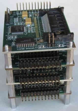
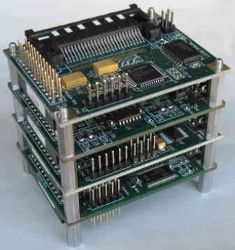
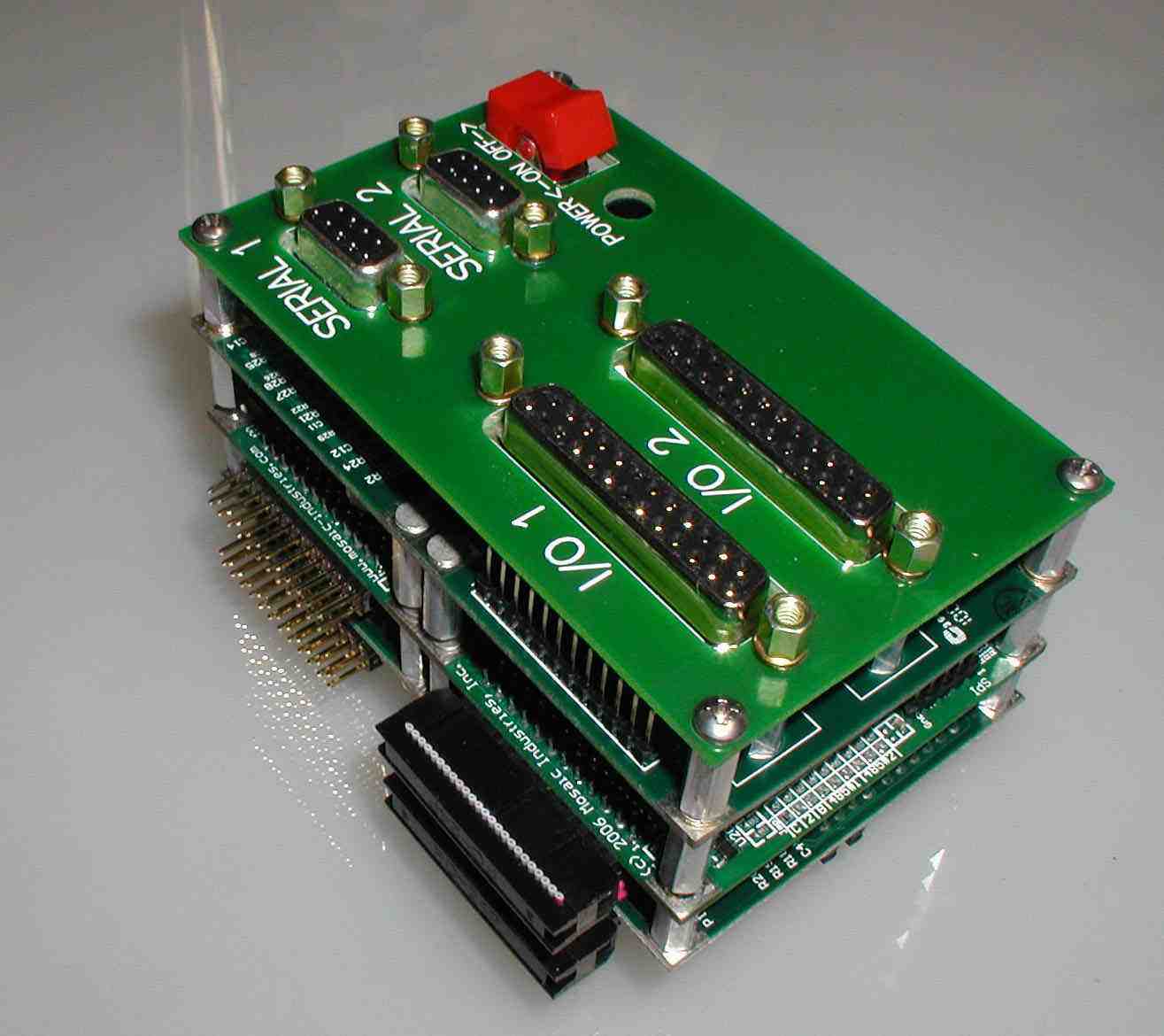
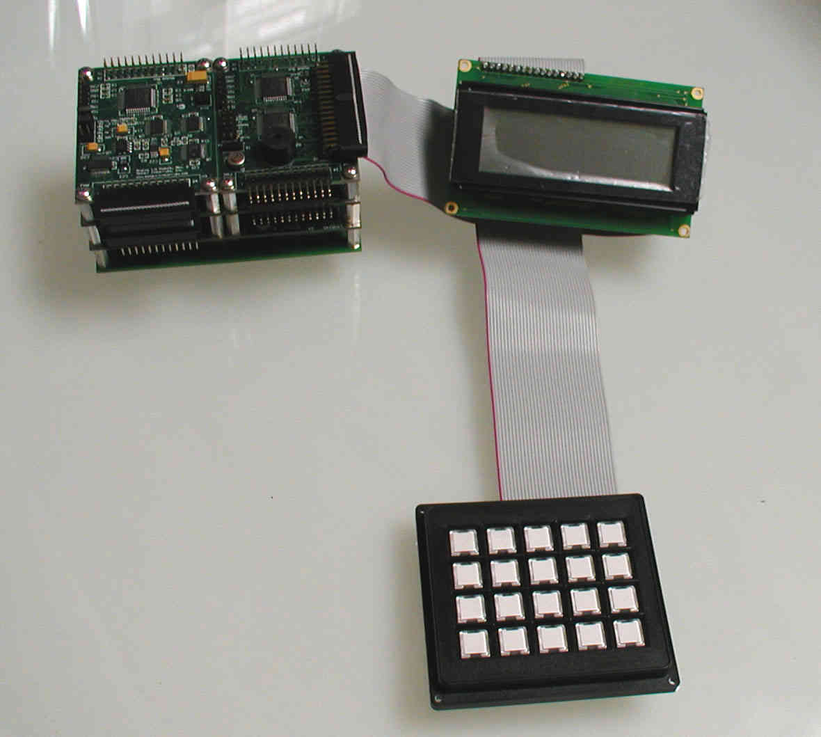
The following photos show several stacks of boards in typical configurations. This first set of photos shows several I/O boards mounted on a QCard Controller. From bottom to top are the following:
- a QCard Controller
- an Analog I/O Wildcard
- a Signal Conditioning Wildcard
- a Compact Flash Wildcard
electronic instrument design | new product development | microcontroller physical dimensions & specifications
