
Loading

|
|
Loading
|
|
|
|
Mosaic embedded designs » Embedded controllers » Accessories » Controlling stepper motors Controlling Stepper Motors Using the Power I/O Wildcard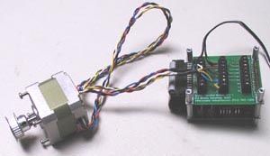
Wiring Stepper Motors to the Power I/O WildcardUse Mosaic's tiny embedded computer, the QCard in combination with the Power I/O Wildcard for a low cost solution to stepper motor control. The Mosaic Stepper Motor has six wires, connected to two split windings as is common for unipolar stepper motors: In use, the center taps of the windings are typically wired to the positive supply, and the two ends of each winding are alternately grounded through a drive circuit to reverse the direction of the field provided by that winding. The Motor Wiring Diagram also illustrates the order of the stator poles in the motor: A, B, A', B'. This is the order in which they must be energized to cause the motor to step in a clockwise direction. Figure 1 shows the pin connections to the Power I/O Wildcard. 
One output of the Power I/O Wildcard is connected to each of the four phases of the motor, a +12V supply is connected to both center taps of the motor and to the V+Field pin of the Wildcard, and the 12V supplies ground return is connected to any of the output field ground pins on the Wildcard. Figure 2 shows the internal drive circuitry of the Power I/O Wildcard, showing four of the eight outputs. Each output is controlled by a power MOSFET whose gate bias is derived from the field supply which must be 4V or greater to provide sufficient gate voltage. Each MOSFET open-drain output is protected with a flyback diode to the V+Field supply and an internal drain-source reverse diode. 
Connecting to a Field SupplyThe Power I/O Wildcard is rated for field voltages to 50V allowing a stepper motor to be driven with supply voltages up to 50 volts. The Mosaic stepper motor is rated for 12V continuous operation assuming that one phase at a time is energized. It can be run at significantly greater voltages if the duty cycle is correspondingly reduced. The Field supply should be wired to the V+Field pin on the Wildcard's Field Header. This connection is necessary to enable the Wildcard's internal diode clamps. These diodes prevent the voltage on the output pins from spiking to above the supply voltage when an output is turned off. If the supply is not connected to the V+Field pin, switching current OFF in inductive loads would cause a voltage spike great enough to cause the output transistors to break down. The stepper motor will run from lower voltages too, but a minimum 4V supply is needed to provide gate bias voltage for the Wildcard's MOSFET transistors. Motor CurrentStepper motor current is limited by winding resistance; each phase draws a maximum of 400 mA from a 12 V supply. This current consumption is well within the 2 A continuous rating of the Power I/O Wildcard's outputs. If the motor is run in high-torque or half-stepping modes as described below it will draw more current from the 12V supply than its continuous power rating can support. Consequently, its must only be run intermittently in those modes to prevent overheating, or turned off between uses. Step Sequences for Full and Half SteppingWhen current is applied to one winding of the motor, the rotor (under no load) snaps into alignment with the stator poles corresponding to the energized winding. It will hold that position against an applied mechanical load, at least until the load exceeds the holding torque of the motor. At that point the rotor would slip, and try to catch at the next equilibrium point corresponding to the energized winding, four steps away. Consequently, when they slip stepper motors don't slip by one step, but by multiples of 4 steps, to one of the equilibrium positions. For any pattern of winding actuation a 200 step-per-revolution motor has 50 equilibrium positions. To rotate this motor continuously, we just apply power to the four phases (or windings) in sequence. We will assume positive logic, where a logic 1 means turning ON the current through a motor winding. This is the way the Power I/O Wildcard works, with a logic 1 turning ON an open-drain output, forcing the output to a low voltage and sinking current Full Stepping (or Wave Stepping)The following control sequence will step the motor clockwise one full step at a time:
Table 1 Each row represents the state of actuation of the four windings, successive rows indicate successive times. Note that there are four steps to a full waveform on each winding, with the fifth step repeating the first. The output byte represents the hexadecimal data byte that is sent to the Power I/O Wildcard. Only the lower nibble (four bits) are used. Two motors, corresponding to two axes of motion, could be controlled by a single Power I/O Wildcard by using the upper nibble for a second motor. Full stepping with only one phase energized at a time is also called wave stepping. High Torque Full SteppingEnergizing two adjacent phases provides greater torque. When two adjacent poles are turned ON together the rotor turns to just half-way between the two poles, with both poles exerting force. Twice the current is required, and the forces sum to provide a torque 1.4 times greater than that provided by energizing only one phase at a time. The following sequence provides high-torque full stepping:
Table 2 Note that the two halves of each winding are never energized at the same time, but both windings are energized simultaneously. The two sequences shown above will rotate a permanent magnet one step at a time. The full-stepping sequence of table 1 only powers one winding at a time; thus, it uses less power. Half SteppingInterleaving the above sequences provides for half stepping. A first winding is energized, aligning the rotor with a particular pole. Then that pole and an adjacent pole are both energized aligning the rotor halfway between them. Then the second pole is energized alone, aligning the rotor with it, and so on. Half stepping provides 400 steps per revolution and smoother motion. The following table provides an 8-step half-stepping sequence:
Table 3 Steppers move more smoothly and are more resistant to resonance effects when half-stepping. Shaft oscillation occurs when the rotor snaps to the next winding during full stepping. The shaft first overshoots, then undershoots, continuing a decaying oscillation. If the load on the shaft happens to have a harmonic period that matches the rotor's oscillation, a resonance develops between the motor and the load. This can destroy the stepper's ability to rotate at certain rates. While still there, these resonance effects are much less pronounced when half-stepping. Micro-SteppingPerhaps the name "stepper" is a misnomer; this type of motor was originally conceived a century ago by the famous inventor Nikola Tesla to run on AC synchronous power. Instead of using smoothly varying AC, if DC is applied first to one winding, then to the next, the motor moves in step fashion, hence the name. However, instead of providing a fixed current into each winding, we can approximate AC drive by varying the DC current to mimic a sinusoidal waveform. This type of drive is called micro-stepping. Half-stepping is the most simple case of microstepping - equal current is applied to two adjacent poles to align the rotor halfway between the poles. But if different currents are applied to the two adjacent poles we can in principle position the rotor anywhere we want between the two poles. For example, applying current to second pole that is 60% of the first current will position the rotor one quarter of the way between the two poles. Micro-stepping is usually accomplished by pulse width modulating (PWM) the currents in the windings to attain intermediate current values other than full ON and full OFF. To provide continuous motion between the two poles we would use PWM to ramp down the current to the first pole, following a cosine wave, while simultaneously ramping up the current to the second, following a sine wave. Because of the inverse square nature of the electromagnetic force, moving smoothly between two poles calls for a cosine/sine current pattern to be applied to the their respective windings. While we could theoretically divide the step as finely as we like, there are practical limitations. These are caused by absolute tooth error (the variation in spacing of the rotor poles), typically about 1/25 of a full step, and a deflection error caused by torque loading. The deflection error is at a minimum when the rotor is positioned on a winding and at a maximum when positioned between windings. If the torque loading is 10%, then the shaft's error when between windings will be 10% of a full step. Microstepping at eight or ten microsteps per full step is a reasonable compromise between smoothness and rotor position accuracy. More microsteps can translate into a smoother motion, but will not likely result in increased rotor position accuracy under load. For insignificant loads micropositioning can be better, but still no better than the absolute tooth error. Stepping SpeedThe maximum stepper motor speed is limited by the inductance of the windings. As the computer switches current to the windings ON and OFF, the rate of current change is limited by the winding inductance. When the winding is switched ON the current increases at an initial rate given by dI/dt = V/L and is eventually limited by the winding resistance. At high speeds there isn't enough time for the current to attain its maximum. When the source of the current is switched OFF, the current is diverted through the flyback protection diodes and internal MOSFET diodes and decreases only slowly, at a rate determined by the small voltage across the diodes, effectively braking the motor. The result of these effects is ever lowering torque as the motor spins faster. There are several ways to increase top speed. A zener diode may be used in series with the flyback diodes to increase the flyback voltage across the winding, allowing the current to decay more rapidly, while still protecting the switching transistors. Further, a greater supply voltage can be used to quickly ramp up the winding current, followed by PWM switching to limit the average current to a safe level. Example SoftwareThe FORTH program at this link illustrates driving the stepper motor from the Power I/O Wildcard. The Wildcard should be mounted on Wildcard Port 0 with its address jumpers set to 1, providing a Wildcard address of 1. The stepper motor is connected as shown in the wiring diagram above. Home | Site Map | Products | Documentation | Resources | Order | About Us Motion Control | Stepper Motor Control | PWM Controller | |||||||||||||||||||||||||||||||||||||||||||||||||||||||||||||||||||||||||||||||||||||||||||||||||||||||||||||||||||||||||||||||||||||||||||||||||||||||||||||||||||||||