
Loading

|
|
Loading
|
|
|
|
Mosaic embedded designs » Embedded controllers » Stepper motor control » Stepper motor specifications The Mosaic Stepper Motor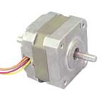
The Mosaic stepper motor (part no. STEPMOT-1) is a four phase, unipolar, permanent magnet stepper motor. It is a standard size, 200-steps-per-revolution, NEMA 17 (1.7 in. square footprint, 5 mm shaft diameter), 12 V motor. This motor, like most stepper motors is a permanent magnet motor. The Mosaic stepper is typical of common high resolution motors - a full revolution requires 200 steps, while each step turns the shaft only 1.8° for a full step, or 0.9° in half-stepping mode. This sized motor is commonly used in household appliances, medical equipment, stage lighting devices, and in various industrial control applications. The following are the physical and electrical specifications of the motor:
The motor has six wires, connected to two split windings as is common for unipolar stepper motors. Figure 1 shows the connection diagram for the six leads. 
In use, the center taps of the windings are typically wired to the positive supply, and the two ends of each winding are alternately grounded through a drive circuit to reverse the direction of the field provided by that winding. The Motor Wiring Diagram also illustrates the order of the stator poles in the motor: A, B, A', B'. This is the order in which they must be energized to cause the motor to step in a clockwise direction. The motor physical dimensions are shown in Figure 2. 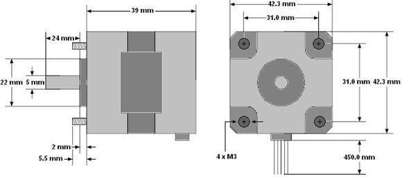
Do you need stepper motor control? For details go to
Ordering Information
Home | Site Map | Products | Documentation | Resources | Order | About Us Stepper Motor Control | Unipolar Four Phase Stepper Motor | Mosaic Stepper Motor Specifications |