|
|
The C Programmer’s Guide to the QVGA ControllerTable of ContentsPART 1 GETTING STARTED Introduction. How to Use This Manual Chapter 1: Getting to Know Your QVGA PART 2 PROGRAMMING THE QVGA CONTROLLER Chapter 3: The IDE: Writing, Compiling, Downloading and Debugging Programs Chapter 4: Making Effective Use of Memory Chapter 5: Programming the Graphical User Interface Chapter 6: Real Time Programming Chapter 7: Failure and Run-Time Error Recovery Getting Started and Getting Stopped - Restarts and Resets Power Fail Monitor - Recovering from Brown-outs and Power Loss The COP Watchdog Timer and Clock Monitor PART 3 COMMUNICATIONS, MEASUREMENT, AND CONTROL Chapter 8: Digital and Timer-Controlled I/O Chapter 9: Data Acquisition Using the QVGA Controller Chapter 10: Outputting Voltages with Digital to Analog Conversion
Chapter 11: Serial Communications Chapter 12: The Battery-Backed Real Time Clock PART 4: PUTTING IT ALL TOGETHER Chapter 13: A Turnkeyed Application PART 5: REFERENCE DATA Appendix A: QVGA Electrical Specifications |
Chapter 7 Chapter 7: Failure and Run-Time Error RecoveryAa variety of useful hardware features of the 68HC11F1 enhance its real-time capabilities and enable recovery from failures: The processor’s two external hardware interrupts, /XIRQ and /IRQ, may be used by external devices to request immediate service. Three nonmaskable interrupts cause a hardware reset: the external reset, the COP, and the clock monitor. The main reset is activated on power-up or when the /RESET pin is pulled low for more than 4 machine cycle. Enabling the computer operating properly circuit, COP, sets up a watchdog timer that resets the processor unless a special register is periodically updated. This provides a means of recovering from crashes in an embedded application. Use of the COP feature requires installation of an autostart routine which services the COP. The clock monitor backs up the COP by resetting the machine if the system clock fails. STOP and WAI instructions are available to put the CPU in low power modes with different degrees of power savings A buffered clock signal, 4xOut, can be used to synchronize additional devices with the QED Board’s processor Finally, an on-board DIP switch allows selection of the standard operating mode or the special cleanup mode.
Getting Started and Getting Stopped - Restarts and ResetsExternal Hardware ResetsThe main reset interrupt of the 68HC11 processor is activated upon power-up or when the active-low /RESET signal is pulled low. The processor does not distinguish between a power-on reset and a reset caused by a low level on the /RESET input pin; both result in the same hardware initialization and software restart sequence. The /RESET line is normally held high by a pull-up resistor. You can pull the /RESET line low by toggling the reset switch, DIP switch #7. You can also connect a momentary contact switch between /RESET and ground; the /RESET signal is available on both the Address/Data connector and the Digital I/O connector. Moreover, any peripheral device can reset the processor by driving the /RESET signal low for at least 2 microseconds using an open-collector output. Both the active-low /RESET signal is controlled by the power monitor circuitry. On power-up, the monitor asserts the reset signal until the positive supply has stabilized above 4.5 Volts. Internal ResetsThe 68HC11 resets itself when a failure condition is detected by either the computer-operating-properly (COP) or the clock monitor circuit. When either of these failure conditions occur, the processor drives the /RESET line low for less than 4 machine cycles to reset itself and any peripherals that are connected to the /RESET line. The processor then determines which failure (COP or clock monitor) caused the reset, and branches to the associated service routine. QED-Forth initializes the interrupt vectors for the COP and clock monitor to perform the standard restart sequence, and the programmer may change the vectors if desired. The operation of the COP and clock monitor are described in the following sections. Power Fail Monitor – Recovering from Brown-outs and Power Loss
Detection of Impending Loss of PowerThe QVGA Controller has a power fail monitoring circuit shown in Figure 7‑1 that can be used to warn the application program of an impending power failure. The processor then has a short period of time in which necessary cleanup and data saving operations can be performed before the processor shuts down.
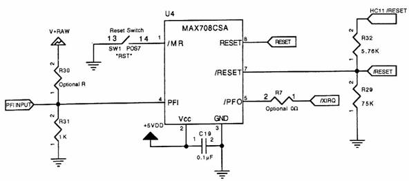
Figure 7‑1 The MAX708CSA Power Fail Input and Power Fail Output circuitry. Other circuitry not related to the power-fail detection is not shown here. By installing an appropriate resistor, you can select the supply voltage at which the power fail signal is asserted. The power fail warning can be configured to generate an nonmaskable interrupt, /XIRQ. This allows the application program to perform any required "cleanup" tasks (such as saving crucial status information in battery-backed RAM) before power is lost. The following 3 steps configure the power fail feature of the QVGA Controller: 1. Connect PFI Input (pin 21 on the Digital I/O Connector) through an external resistor to the external power source that you wish to monitor. Resistor value selection is discussed below. Volume OEM users can install the resistor as a surface-mount device at position R30 on the QED-Flash Board. 2. Install a zero-ohm resister at location R7, located just above the flash socket (S1) on the top of the QED-Flash Board, to connect the power fail output to the processor's XIRQ input. 3. Enable the nonmaskable interrupt after every reset. When the PFI Input (pin 21 on the Digital I/O Connector) falls to less than 1.25 V, the Power Fail Output (/PFO) of the MAX708 chip in Figure 7‑1 goes active low, triggering the /XIRQ interrupt if it is enabled and if R7 is installed. The value of the user-supplied resistor between the PFI input and the monitored voltage supply named V.supply is calculated using a simple voltage divider equation as, Eqn. 7‑1 R = ( V.supply / 1.25 ) - 1 where R is expressed in units of kW. For example, to configure a power fail warning when V.supply goes below 6V, choose R30 = 3.8kW. Typically, V.supply is the V+raw input to the QED Board, but any power supply voltage can be monitored using this circuit. The /Power.Fail signal is an active-low output. It is asserted (it goes low) when the +5 Volt digital supply (denoted as +5V on the connector diagrams) falls to within 0.15 Volts of the voltage at which the /RESET signal is asserted. Assuming a current drain of 100 mA, the time it takes the voltage to drop 0.15 Volts equals 1.5 microseconds per microfarad of filter capacitance. A relatively small filter capacitance of 22 µF is installed across the +5V digital supply, so if no additional capacitance is added to the board only 22 * 1.5 = 33 microseconds are available between the power fail warning and the shutdown of the processor if there is a sudden disconnect of power. With an interrupt latency of 17 usec (see Chapter 3), only 16 usec is available to the /XIRQ interrupt service routine to perform cleanup operations. To increase the available time, simply connect a capacitor from the +5V supply to digital ground (labeled DGND). +5V and DGND are available at the Power connector, Address/Data bus connector, and the Digital I/O connector. For example, using the 1.5 microseconds per microfarad relationship, a 470 µF capacitor would allow the /XIRQ interrupt approximately 700 microseconds to “clean up” and save any required data before the processor is shut down by the /RESET signal. Eqn. 7‑2 cleanup.time = [ 1.5 us/µF ] * [ 470 µF ] = 700 microseconds In addition to installing the filter capacitor, you should connect the /Power.fail output (pin 21 on the Digital I/O connector) to the adjacent /XIRQ input (pin 19 on the Digital I/O connector).
Your /XIRQ service routine should finish with an endless loop; simply waiting for power to go down. If we allowed the interrupt service routine to terminate, it would be immediately called again because the /Power.fail signal would still be active -- only this time there would be less time to perform the required clean up! If your clean-up routine has to perform a lot of functions, consider using a large filter capacitance and/or assembly coding the /XIRQ service routine. Storage of values in EEPROM is not recommended as part of a power-fail clean-up routine, as 20 msec are required to modify each EEPROM byte; instead, consider saving key transient parameters in battery-backed RAM. If you want crucial information in the EEPROM, save it periodically before there is a chance that power goes down. The COP Watchdog Timer and Clock MonitorIn many embedded control applications, it is important that processor crashes be detected quickly so that the system can rapidly be returned to a proper operating condition. The Computer Operating Properly subsystem, also known as a “watchdog timer” or “COP”, provides this capability. It gives the programmer a way to force a processor reset if an application program crashes or gets lost. When enabled, the COP resets the processor if the application program fails to periodically update a specified register within a predetermined time-out period. The COP time-out period is programmable to any of four values between 8 msec to 0.5 seconds. To use the COP, design and debug an application program that, in addition to performing all of its normal tasks, periodically writes a 2-byte pattern to the COP reset (COPRST) register as described below. The specified pattern must be written before the COP “times out”. Then install the application as an autostart routine using the QED-Forth word AUTOSTART, and enable the COP. If the application program ever allows the time-out period to be exceeded without writing the specified pattern, the COP resets the processor. Presumably the pattern will not be properly written if the processor crashes for any reason, so the COP provides a way of automatically resetting the processor to recover from crashes. Then, because the application program has been installed as an autostart routine, the application is automatically restarted when the COP forces a reset. Be Careful with the COPBefore enabling the COP, make sure that a debugged application program that properly updates the COPRST register has been installed as an Autostart() or PriorityAutostart() routine. If the startup program is improperly designed so that it is unable to service the COP on time, the COP will reset the machine, thereby invoking the startup program again, and leading to an infinite series of COP resets. If you find yourself in this situation you can return the QVGA Controller to its “pristine” state by entering the special clean-up mode: turn DIP switch 6 On, toggle DIP switch 7 On then Off, then turn DIP switch 6 back Off to resume normal operation with the COP disabled and any autostart routine removed. The COP feature should prove trouble-free as long as the application program is: fully debugged; capable of updating the COPRST in a timely fashion; and, installed as an autostart routine. Configuring the COPThree bits are used to configure and enable/disable the COP. They are named CR0, CR1, and NOCOP. CR0 and CR1 are located in the OPTION register. These bits determine the amount of time which can elapse between updates of the COPRST register by the application program. If the time-out period is exceeded, the COP forces a reset. The four available time-out periods are: Table 7‑1 COP Time-out Period
The CR1 and CR0 bits in the OPTION register may be modified only during the first 64 cycles after a reset. The QED-Forth word INSTALL.REGISTER.INITS makes it easy to specify a value that will be automatically stored into the OPTION register after every reset; consult its glossary entry for details, or see the coded example presented below. The third control bit is called NOCOP and is located in the CONFIG register. The QED-Board is shipped with this bit set so that the COP is disabled. To enable the COP, clear this bit; the example code presented below demonstrates how to do it. The CONFIG register’s contents are non-volatile, and so are maintained even after the processor has been powered down. Servicing the COPServicing the COP is accomplished by writing 55H and AAH to the COPRST register. Although the order of the writes is important, the number of intermediate instructions between them is inconsequential. The two writes must be performed before the time-out period has elapsed. Once AAH has been stored, the COP will need to be serviced again before the next time-out period has elapsed.
The Clock MonitorThe clock monitor provides a second level of security by monitoring the main system clock and resetting the processor if the clock signal disappears or oscillates too slowly. The clock monitor does not initiate a reset as long as the E-clock frequency is greater than 200 kHz (the E-clock frequency is one quarter the frequency of the on-board crystal). A reset is always triggered at E-clock frequencies below 10 kHz, and may be triggered at frequencies as high as 200 kHz. The clock monitor is primarily used as a backup for the COP. The COP relies on the clock’s presence for reliable operation, and the clock monitor can ensure that the processor is safely reset if the clock fails. Enabling the clock monitor is accomplished by setting the CME (clock monitor enable) bit in the OPTION register. This bit may be set or reset at any time. A second bit named FCME (force clock monitor enable) is also involved. When the FCME bit is in its default state of 0, the bit has no effect, and when FCME is set, the clock monitor feature cannot be disabled until a reset occurs. We will assume that FCME is 0, and that the CME bit controls the clock monitor. See MC68HC11F1 Technical Data Manual, p.6-5 for further details. Note also that if the clock monitor is enabled, a STOP assembly instruction will trigger a reset because it stops the clock, as discussed in the “Low Power Modes” section below.
Processor Operating ModesLow Power ModesThe 68HC11F1 has two low power modes. These modes are enabled by assembly instructions STOP and WAI (wait). The STOP command puts the CPU into its lowest power-consumption mode by stopping all clocks, thereby stopping all processing (MC68HC11F1 Technical Data Manual, p.6-17). If the clock monitor is enabled, a reset will be triggered when the clocks stop due to a STOP instruction. To use a STOP instruction when the clock monitor reset is enabled, disable the monitor before the STOP instruction, and re-enable it after returning from the STOP. Pulling either /RESET, /IRQ or /XIRQ low wakes the processor up after a STOP instruction. Pulling the reset line low awakens the CPU and performs the standard reset startup sequence. Pulling /XIRQ low to awaken the CPU triggers a normal /XIRQ interrupt if the X bit in the CCR register is clear (i.e., if /XIRQ interrupts are enabled). After execution of the /XIRQ interrupt handler, processing returns to the instruction following the STOP command. If the X bit is set, (i.e., if /XIRQ is not enabled), pulling /XIRQ low awakens the CPU, but processing will begin at the instruction following the STOP instruction, and no interrupt will be called. For the CPU to be awakened by the /IRQ line going low, the I bit in the CCR register must be clear so that interrupts are globally enabled. When /IRQ goes low and the I bit is clear, execution begins with the /IRQ handler and then executes the code following the STOP instruction. The STOP instruction is executed as a NOP unless the S bit in the CCR is cleared. After clearing the S bit, any occurrence of a STOP instruction puts the CPU into its lowest power mode. After each reset or restart, QED-Forth leaves the S bit in the CCR in its default set position, meaning that the STOP mode is disabled.
WAI Low Power ModeThe WAI instruction also puts the 68HC11F1 in a low power mode. However, clocks are not disabled in the wait mode, so power consumption is greater than the STOP mode. After a WAI instruction, the machine state is stacked and processing stops. Power savings can be increased by setting the I bit in the CCR and disabling the COP. Further savings can be achieved by disabling the on-chip subsystems, including executing A/D8.OFF to turn off the A/D (MC68HC11F1 Technical Data Manual, pp.6-17...6-18). The WAI low power state can only be exited by an unmasked interrupt or by pulling the /RESET pin low. When an unmasked interrupt occurs, (for example /IRQ or /XIRQ goes low, the COP is not serviced, clock monitor failure or reset occurs), the appropriate interrupt handler is executed and then processing continues with the instructions following the WAI. Implementing the WAI lower power mode is accomplished by simply executing WAI.
Summary of Low Power ModesIn sum, power can be saved by putting the CPU in a low power mode while processing is not required. The 68HC11F1 has two low power modes with different degrees of savings. Both modes are terminated by unmasked interrupts. While the WAI instruction can be called without any preparation, the STOP instruction must be enabled by clearing the S bit of the CCR register. Operating Modes of the 68HC11F1 CPUThe 68HC11F1 microcontroller has four operating modes: expanded nonmultiplexed, special test, single chip, and special bootstrap modes (M68HC11 Reference Manual, chapter 3 and MC68HC11F1 Technical Data Manual, pp.2-1...3). The standard operating mode is expanded nonmultiplexed, meaning that the processor has access to expanded memory beyond its on-chip memory, and that the address and data lines are not multiplexed together (as they are on other members of the 68HC11 family). The QED Board also makes use of the special test mode, renaming it the “special cleanup” mode. This mode makes it possible to rapidly recover from any programming error that causes repeated machine crashes. The single chip mode takes away the ability of the processor to address external memory, and special bootstrap allows startup code to be inserted into the processor; these two modes are not used on the QED Board. The processor’s operating mode is determined by the states of two pins named MODA and MODB (refer to the schematic in Appendix A). On the QED Board, MODA is always high and MODB may be pulled LOW by turning onboard DIP switch #5 ON; this invokes the special cleanup mode. When DIP switch #5 is in its standard OFF position, the board is in the standard operating mode. Special Cleanup ModeThe Special Cleanup Mode is useful if a buggy startup routine has been installed (using the AUTOSTART or PRIORITY.AUTOSTART words) or if invalid register initializations have been specified (for example, using the INSTALL.REGISTER.INITS word). To recover from these problems, simply enter the special cleanup mode by keeping turning DIP switch #6 ON, and then powering up the board or actuating the reset button (DIP switch #6), then turning DIP switch #6 back OFF. This completely re-initializes the system software to its “pristine” state, and displays the QED Forth startup message at your terminal. The special cleanup mode is also discussed in the “Interrupts and Register Initializations” chapter in the QED Software Manual.
|
Home|Site Map|Products|Manuals|Resources|Order|About Us
Copyright (c) 2006 Mosaic Industries, Inc.
Your source for single board computers, embedded controllers, and operator interfaces for instruments and automation