|
|
The C Programmer’s Guide to the QVGA ControllerTable of ContentsPART 1 GETTING STARTED Introduction. How to Use This Manual Chapter 1: Getting to Know Your QVGA PART 2 PROGRAMMING THE QVGA CONTROLLER Chapter 3: The IDE: Writing, Compiling, Downloading and Debugging Programs Chapter 4: Making Effective Use of Memory Chapter 5: Programming the Graphical User Interface The Structure Of The GUI Toolkit Transferring Your Images to the QVGA Controller Expanding the GUI Toolkit’s Objects and Methods Chapter 6: Real Time Programming Chapter 7: Failure and Run-Time Error Recovery PART 3 COMMUNICATIONS, MEASUREMENT, AND CONTROL Chapter 8: Digital and Timer-Controlled I/O Chapter 9: Data Acquisition Using the QVGA Controller Chapter 10: Outputting Voltages with Digital to Analog Conversion
Chapter 11: Serial Communications Chapter 12: The Battery-Backed Real Time Clock PART 4: PUTTING IT ALL TOGETHER Chapter 13: A Turnkeyed Application PART 5: REFERENCE DATA Appendix A: QVGA Electrical Specifications |
Chapter 5 Chapter 5: Programming the Graphical User InterfaceThe Graphical User Interface (GUI) Toolkit is a suite of programming tools that gives you the ability to build an informative and interactive graphical user interface to monitor and control your instrument. This chapter Introduces the structure of the GUI Toolkit; Takes you on a step-by-step guide to building your interactive application; and Provides you with detailed descriptions of each component of the GUI Toolkit. The Structure Of The GUI ToolkitA graphical user interface is created from building blocks such as bitmapped images and ASCII strings. These building blocks, or data, must be organized in an intuitive way so users can easily run your instrument. Object oriented concepts are the key to organizing this data and make it easy for you to design and implement your user interface. Object oriented programming allows you to organize data hierarchically based on objects and manipulate the data using methods. With the GUI Toolkit, it is simple to create elementary objects such as graphics that contain bitmapped image data and textboxes that contain ASCII string data. You can load those objects into other objects such as screens so that they can be shown on the display. You can create yet another type of object, a control, which can execute functions that acquire data from a user or actuate hardware when a user touches the touchscreen. A button is one kind of a control. A Closer Look At ObjectsThe two concepts of object oriented programming essential to modern programs with user interfaces are “Objects” and “Events”. An object is an association of properties and methods, and may respond to events. An event is an external action that prompts an object into action. GUI Toolkit objects that can respond to events are called controls. PropertiesProperties describe an object’s physical attributes like its size, location, or image. Objects contain a data structure that holds its properties. Properties generally don’t do anything by themselves; they are more like read/write variables. However, properties may qualify the object’s behavior when the object does do something or has something done to it. Some properties may be read only while others may be read/write. GUI Toolkit properties are always 32-bit numbers and are accessed or modified by calling the methods Get_Property or Set_Property. Set_Property requires a reference to an object, its property, and the new value, while Get_Property requires a reference to an object and its property as parameters and returns the property value. MethodsMethods are actions the object can do or have done to it. Many methods, like Load, are overloaded; that is, they are applicable to several different types of objects. For example, you can load buttons, graphics, and textboxes into a screen. Overloaded methods allow you to use a single simple syntax with respect to many different objects. EventsEvents are external actions that an object responds to by executing a user defined function called an event procedure. Objects automatically recognize a predefined set of events, it is up to you to decide if and how they respond to those events. You specify the event procedure called when the event happens (or fires) by storing your function into the appropriate property using Set_Property. Event procedures are written, for example, to specify the program actions that occur in response to the press of a button. The GUI Toolkit ObjectsThe following table lists the objects in the GUI Toolkit.
Some of these objects are created when you initialize the GUI Toolkit while others are created by functions that you write. All GUI objects reside in their own task with their own heap and some respond to events. In the next section, we’ll show you how to create your user interface and then how to write your application using the GUI Toolkit. Building Your ApplicationIn this section, we’ll explore the GUI Toolkit in the order in which you would typically build your application. We’ll show you how to: Design and create your user interface on a PC; Transfer the images that you created for your user interface from the PC to the QVGA Controller; Write your application using the demo program as a reference guide; Handle errors; and, Expand the capabilities of the GUI Toolkit. The demo program shows you how to build a multitasking application with three simple screens. The first screen is a numeric keypad that allows you to enter up to 20 digits and render them in a textbox. The second screen displays three different size Courier New fonts ranging from the default font of 8 pixels wide by 10 pixels tall to a large font that is 32 pixels wide by 40 pixels tall. The third screen plots an 8-bit A/D input every 10 seconds. As we describe each part of the GUI Toolkit, we’ll use the numeric keypad screen of the demo to illustrate the important concepts. Designing Your User InterfaceBefore you start coding your application, it’s a good idea to sketch out how you want your user interface to look. Figure 5‑1 shows a rough sketch of the first screen of the demo program. Sketching out your user interface before you start programming will help you to think about how you want your application to be organized and how you want to present information to your user.
Figure 5‑1 The sketch of the first screen of the demo program. Drawing Your ScreensOnce you’ve sketched out and designed your user interface, you need to create bitmapped images of your interface using an image-editing program. Images may be created using Microsoft Paint, which is included with all versions of Windows. You can also use other image-editing programs such as Corel Draw, Photoshop, and Paint Shop Pro. In this section and throughout this chapter, we provide step-by-step instructions for creating and manipulating images using Photoshop. However, all of the image-editing programs have similar tools and functionality. For example, the pencil tool in Photoshop is simply called the pencil in Paint and the line tool in Photoshop is called the line in Paint. Thus, the steps listed in the examples, although specific to Photoshop, apply to all image-editing programs. To create an image of a screen from your sketch using Photoshop: 1. Create a new file with a width of 320 pixels and a height of 240 pixels, a resolution of 72 pixels per inch, and using the bitmap image mode. 320x240 is the size of the display and the size of a screen. The resolution is not important because it refers to the number of pixels per inch for the monitor. However, the image mode is important and must be set to bitmap if you are using a monochrome or EL display. This configures the image to have one bit per pixel. 2. Draw all lines using the pencil tool with a brush size of one pixel. The line tool, paint brush tool, and airbrush tool are also useful in drawing shapes and patterns. 3. Draw text using the type tool. 4. Save the image as a windows bitmap. A dialog box may appear informing you that some image data, such as printer settings, cannot be saved with this format. This does not effect the image so you can just click on OK. The image that we created based on the sketch in Figure 5‑1 is shown in Figure 5‑2 .
Figure 5‑2 The bitmap image of the first screen of the demo program that was created using Adobe Photoshop. Creating Your ImagesOnce you have created the screens for your user interface, you need to ungroup them. Ungrouping the screens into smaller images will allow you to save space in Flash memory since you don’t want to store images with a lot of white space. It will also allow you to associate the images with individual buttons. To ungroup an image using Photoshop: 1. Select the marquee tool; 2. Left click on the upper left corner of an image you want to ungroup and drag the mouse pointer to the lower right corner of the image. This will create a box with a moving dashed line around the image; 3. Note the location of the upper left corner of the image; this location will be needed when you want to load a graphic containing the image onto a screen; 4. Under the Edit Menu, select the cut option to move the image to the clipboard. The image will disappear from the screen; 5. Under the File Menu, select the create new file option; 6. Name the file, based on the image. The height and width will automatically be set to the height and width of the image that is in the clipboard; 7. Under the Edit Menu; select paste; and, 8. Save the ungrouped image in the Windows bitmap format. The width of an image must be a multiple of 8 pixels and the image must be positioned on an 8 pixel horizontal grid in a screen. Finer horizontal pixel placement and image widths would require bit shifting of each byte of the image every time it is drawn, significantly slowing performance of the GUI Toolkit. There are no limitations on the height of an image or the placement of an image in the vertical direction.
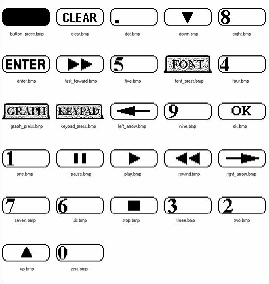
Figure 5‑3 The images included with the demo program that you can use in your application. The demo program also provides a set of images that you can use with your application. The images are shown in Figure 5‑3 . Transferring Your Images to the QVGA ControllerOnce you have ungrouped all the images for your user interface, assemble them into a single directory. Images must be processed before you can use them with the GUI Toolkit; Mosaic’s Image Conversion Program concatenates images into a single text file called an Image Data File. The Image Data File is stored in the same directory as your images and when it is transferred to the QVGA Controller, it stores your image data in RAM and then copies it into Flash. You must transfer the Image Data File using QEDTerm, Mosaic’s Terminal Program, to the QVGA Controller before you transfer your application code. For more information on the Image Conversion Program, see the section on the Image Conversion Program . The Image Header FileAn Image Header File is also created with the Image Conversion Program and stored in the same directory as your images. The Image Header File associates the names of your images with the location of their image data in Flash. The Image Header File must be included in your application in order for you to create graphic objects. The following shows the first few lines of the Image Header File used by the demo. The Image Header File defines a few constants, named after the image files down.bmp, button_press.bmp, and one.bmp shown in Figure 5‑3 . The constants contain the addresses of the image data in Flash memory on the QVGA Controller. For more information on the memory map of the QVGA Controller see Chapter 4: Making Effective Use of Memory[pkc1]. Listing 5‑1 The first few lines of the Image Header File. #define BOTTOM_EDGE_BMP 0x700000 #define BUTTON_PRESS_BMP 0x700110 . . . #define ONE_BMP 0x705806
Coding Your ApplicationOnce you have designed and built the user interface for your application and you have transferred the images to the QVGA Controller, you can start writing the code to animate your instrument. All GUI applications need the following components: The pre-loaded GUI Toolkit driver software; The Image Data and Image Header Files from the Image Conversion Program; An initialization routine that initializes the GUI Toolkit and sets up a task to run your application’s user interface. Routines that create and configure objects; Event procedures that animate controls; and, Routines that load objects onto screens. Each of these components are described in the following sections. The GUI Toolkit Driver SoftwareThe GUI Toolkit driver software is pre-installed on your QVGA Controller. However, you will need to copy the library files (which define constants, structures, and headers for the GUI Toolkit methods) to the same directory as your source code as described below. To reload the driver software, please see section XX. The GUI Toolkit driver software is provided as a pre-coded modular runtime library, known as a “kernel extension” because it enhances the on-board kernel's capabilities. The library functions are accessible from C and Forth. The kernel extension for the GUI Toolkit is available from Mosaic Industries on the Demo and Drivers media (diskette or CD). Look in the Drivers directory, in the subdirectory corresponding to your hardware, in the GUI Toolkit folder. The kernel extension is shipped as a “zipped” file named “packages.zip”. Unzipping it (using, for example, winzip or pkzip) extracts the following files: readme.txt - Provides summary documentation about the library. install.txt - The installation file, to be loaded to COLD-started QED Board. library.4th - Forth name headers and utilities; prepend to Forth programs. library.c - C callers for all functions in library; #include in C code. library.h - C prototypes for all functions; #include in extra C files. Library.c and library.h are only needed if you are programming in C. Library.4th is only needed if you are programming in Forth. The uses of all of these files are explained below. We recommend that you move the relevant files to the same directory that contains your application source code; the references to the library files in the demo assume the library files are in the same directory as the source code. Using the Driver Code with C Move the library.c and library.h files into the same directory as your other C source code files and use the following directive in your source code file:
#include “library.c” This file contains calling primitives that implement the functions in the kernel extension package. The library.c file automatically includes the library.h header file. If you have a project with multiple source code files, you should only include library.c once, but use the directive
#include “library.h” in every additional source file that references the GUI Toolkit functions. Note that all of the functions in the kernel extension are of the _forth type. While they are fully callable from C, there are two important restrictions. First, _forth functions may not be called as part of a parameter list of another _forth function. Second, _forth functions may not be called from within an interrupt service routine unless the instructions found in the file named \MOSAIC\DEMOS_AND_DRIVERS\MISC\C EXAMPLES\forthirq.c are followed. NOTE: If your compiler was purchased before June 2002, you must update the files, qlink.bat and qmlink.bat in your /fabius/bin directory on your installation before using the kernel extension. You can download a zip file of new versions from http://www.mosaic-industries.com/Download/new_qlink.zip The two new files should be placed in c:\Fabius\bin. This upgrade only has to be done once for a given installation of the C compiler.
Using the Image Data and Image Header FilesBefore writing your application code, be sure to transfer the Image Data File, created with the Image Conversion Program, to the QVGA Controller. Then, be sure to include the Image Header File in your application as shown below: Listing 5‑2 The first few lines of the demo program. #include <\mosaic\allqed.h> // Include all of the Mosaic utilities. #include “library.c” // Include the headers for the GUI Toolkit’s methods. #include “image_header.h” // Include constants that define location of your images
Writing Your Application’s Initialization RoutineThe initialization routine of your application needs to initialize the GUI Toolkit and setup a task to control the GUI Toolkit before any GUI Methods are called. Initialize_GUI must be called before any other GUI method! To initialize the GUI Toolkit, call Initialize_GUI, passing it a heap start address and a heap end address as shown in the demo. Listing 5‑3 Initializing the GUI Toolkit #define GUI_HEAP_START 0x0F3000L #define GUI_HEAP_END 0x0F6FFFL . . void main( void ) { Initialize_GUI ( GUI_HEAP_START, GUI_HEAP_END); . . }
Initialize_GUI performs three actions: it sets up a heap memory structure for the GUI Toolkit; it sets up and activates a task for the GUI Toolkit; and it configures several critical objects, called the GUI Toolkit’s pre-instantiated objects. All GUI objects and their associated properties are stored in a heap accessed only by the GUI Toolkit. This GUI Heap can be located in any contiguous block of RAM (i.e. it may span consecutive pages of RAM) but it is typically placed on page 0x0F from 0x3000 to 0x6FFF as shown in the example above. The size of the heap that is needed by the GUI Toolkit depends on your application. As a benchmark, the demo program uses approximately 4k of heap space. Because all objects are stored in the GUI Heap, it is easy to add, modify, or resize objects without worrying about the specifics of their memory allocation. The GUI Toolkit runs in a stand-alone task called the GUI Task. The GUI Task executes an endless loop that: continuously checks to see if new objects need to be created or existing objects need to be modified; polls the touchscreen looking for events; services events when they occur; and, calls Pause. When a touchscreen event occurs, the GUI Task sends a message indicating that the event procedure of the responsible control should be executed. Service_GUI_Events listens for messages from the GUI Task and executes the appropriate event procedure when commanded. Service_GUI_Events must be included in the infinite loop of a task that you create (separate from the GUI Toolkit’s Task) as shown in the following example. This task should also be in charge of creating and initializing the objects for your application. Listing 5‑4 Servicing GUI Events TASK taskbase; . . void GUI_Monitor ( void ) { . . while(1) { . . Service_GUI_Events(); Pause(); } } void main( void ) { Initialize_GUI ( GUI_HEAP_START, GUI_HEAP_END); . . Init_Keypad(); // create & init objects for keypad . . BUILD_C_TASK(0, 0, &taskbase); // build task ACTIVATE( GUI_Monitor,&taskbase); // activate task StartTimeslicer(); // starts elapse time clock, enables interrupts Pause(); // start next task immediately }
The GUI Toolkit is a resource whose access must be controlled. Only the GUI Toolkit (running in the GUI Task) polls the touchscreen, writes to the display, creates objects, or modifies objects. We recommend that you use only one task to run the your application’s user interface so that only one task interacts with the GUI Toolkit. However, if multiple tasks in your application need to use the GUI Toolkit, you must use the resource variable gui_resource to assure that only one task accesses the GUI Toolkit at a time. See section XX for more information on using resource variables or the glossary entry for gui_resource. The GUI Task should have an opportunity to run approximately once every 15 milliseconds. Calling the GUI Task more frequently will not improve performance because the GUI Task polls the processor’s free running counter, TCNT, to assure it is not called more than once every 10 milliseconds. Calling the GUI Task less frequently will not cause any errors but may result in sluggish performance. The GUI Task takes approximately one millisecond to execute if no events occur, no new object needs to be created, and no existing object needs to be modified. When an event fires, the time the GUI Task takes to execute is proportional to the number of items that are loaded onto the visible screen. For a screen with 15 objects, it will take approximately 5 milliseconds to pass the event to the responsible control. Additional time is required if the responsible control has an image that has to be redrawn. The GUI Toolkit’s Pre-Instantiated ObjectsThe GUI Toolkit has a set of special objects that are created and configured only when you initialize the GUI Toolkit. These special objects are called the pre-instantiated objects because they are instantiated or created before the GUI Toolkit starts it’s task. These objects include the GUI Toolkit itself, the display, six predefined screens, the touchscreen, the pen, the buzzer, and the default font. You can not create additional instances of these objects because they are tied to a specific piece of hardware or unique function of the GUI Toolkit. The GUI Toolkit is itself an object with properties that influence the operation of the GUI Task and all other objects. The GUI Toolkit Object is called the GUI TOOLKIT and has properties that determine how objects such as graphics and controls are loaded into screens, whether touchscreen events are serviced, and the behavior of the GUI Task when an error occurs. The Display Object is called the GUI_DISPLAY, and is tied to the physical display. Properties of the GUI_DISPLAY control the behavior of the display such as blanking and inverting. The GUI_DISPLAY contains six pre-instantiated screens called GUI_SCREEN0 to GUI_SCREEN5. A property of GUI Screens is their Visibility property. Only one of the GUI Screens may be made visible at a time. When it is made visible, the other GUI Screens are automatically made not visible and the display suddenly shows the visible screen’s objects. GUI Screens are the only objects that are shown on the physical display. To show an object like a graphic on the display, the object must be loaded into the visible GUI Screen. The visible screen after Initialize_GUI is called is GUI_SCREEN0. The Touchscreen Object is also known as the GUI_TOUCHSCREEN and corresponds to the physical touchscreen. The GUI_TOUCHSCREEN generates events when a user places a finger on the physical touchscreen (press event), while the user continues pressing the physical touchscreen (held event), and when the user removes their finger (release event). Properties of the GUI_TOUCHSCREEN contain the identity and pixel coordinates of the last event. The Pen Object is called the GUI_PEN. This useful tool generates geometric shapes and line drawings on a screen. The GUI_PEN has properties that control how the points and lines are drawn so you don’t have to pass all the optional parameters to the drawing method each time it is called. The Buzzer Object is called the GUI_BUZZER and it is associated with the piezo electric beeper. Properties of the GUI_BUZZER control the length of time of a beep and turn the buzzer on and off. The Default Font Object is called the GUI_FONT and is associated with the 8-pixel wide by 10-pixel tall Courier New font that renders string data in a textbox onto a screen. Creating New ObjectsThe GUI Toolkit also has other objects, like graphics and buttons, that you can create using the New_Object method. New_Object requires one input parameter that specifies the type of object you want to create; GRAPHIC, FONT, TEXTBOX, BUTTON, and PLOT are all valid object types. New_Object returns an integer that you store into a variable. This variable (which we call an object reference because it contains a reference to the object) is used to set properties of the object and perform actions on the object like loading the object onto a screen. The following code from the demo, creates a new graphic object and stores its object reference into a variable named graphicOne. Later, we’ll set the image of the graphic and then configure the “one” button of the keypad to use this graphic as its DRAW_GRAPHIC. Listing 5‑5 Creating a New Graphic. int graphicOne; . . . void Init_Keypad_Images ( void ) { graphicOne = New_Object ( GRAPHIC ); . . . }
Objects can be created but not destroyed. Because objects are stored in the heap, you can only create a finite number of them. Different objects use different amounts of heap space. For example, graphics and fonts only use a few bytes of heap space while plots use hundreds of bytes depending on the size of its buffer. Setting the Property of ObjectsAll objects have their properties set to default values when they are created so that you need to set as few properties as possible to have a fully functional object. However, certain objects like graphics require you to set its image before the graphic can be loaded onto a screen or into a button. In the demo, Init_Keypad_Images creates a graphic and then sets it’s image property using a constant defined in the Image Header File. Listing 5‑6 Setting the Property of a Graphic. int graphicOne; . . . void Init_Keypad_Images ( void ) { graphicOne = New_Object ( GRAPHIC ); Set_Property ( graphicOne, IMAGE, ONE_BMP ); . . . }
Creating and Initializing ControlsNow that you’re familiar with creating graphic objects, we’ll show you how to create a button. To create a button: 1. Use the New_Object method to create a button and store the object reference to the button into a variable. By default, the button will beep when it receives a press event. You can change this behavior by setting the BEEP_ON_PRESS property to GUI_FALSE. 2. Create and define a graphic for the DRAW_GRAPHIC property of the button. A button needs at least one graphic to define it’s size and active area. 3. Create and define a graphic for the PRESS_GRAPHIC property of the button. By defining a PRESS_GRAPHIC that is different from the DRAW_GRAPHIC, you will provide the user with visual feedback for press events, thus enhancing your user interface. 4. Define the PRESS_EVENT_PROCEDURE for the button. Writing event procedures is covered in the next section. 5. Initialize the DRAW_GRAPHIC, PRESS_GRAPHIC, RELEASE_GRAPHIC, and PRESS_EVENT_PROCEDURE properties of the button using Set_Property. Typically, the RELEASE_GRAPHIC is set to the DRAW_GRAPHIC to provide visual feedback for release events. The following code shows the Init_Keypad_Buttons function from the demo that illustrates how to create a button that, when pressed, will beep, show a filled-in image of button on the display, and execute an event procedure. When the button is released, the filled-in image of the button is replaced with the DRAW_GRAPHIC. Listing 5‑7 Creating and Initializing a Control. int buttonOne; . . . void Init_Keypad_Buttons ( void ) // Init_Keypad_Images() must be called before this routine { buttonOne = New_Object( BUTTON ); Set_Property(buttonOne, DRAW_GRAPHIC, (long) graphicOne); Set_Property(buttonOne, PRESS_GRAPHIC, (long) graphicButton_Press); Set_Property(buttonOne, RELEASE_GRAPHIC, (long) graphicOne); Set_Property(buttonOne, PRESS_EVENT_PROCEDURE, (long) one_event_procedure_ptr); . . . }
Remember that all properties are 32-bits in size so when setting any of the graphic properties of the button, the graphic object reference must be cast into a 32-bit number. Writing Event ProceduresEvent procedures are functions that you write to animate your controls. Event procedures cannot take any parameters or return any values, but they can set variables and call other GUI methods like Clear and Refresh. In the demo, the event procedure for the one button of the keypad must write the number one into the textbox of the keypad at the correct position and then refresh the keypad screen so the new number will appear. The following shows the code for the one button’s event procedure. Listing 5‑8 Writing the Event Procedure. // Define a constant to represent the maximum number of numbers we can enter // using the keypad. #define BUFFER_LENGTH 20 // Declare a variable that contains the next position we’re writing to the textbox int buffer_pos; . . . void One_Event_Procedure ( void ) { if(buffer_pos < BUFFER_LENGTH-1) { STRING_TO_TEXTBOX(textboxBuffer, " 1", 0, buffer_pos); buffer_pos++; Refresh(GUI_SCREEN0); } } // We need to store the address of the event procedure into a function pointer which // will be used in Set_Property. #include “begin_event_procedure_pointers.h” . . . xaddr (*one_event_procedure_ptr)(void) = One_Event_Procedure; . . . #include “end_event_procedure_pointers.h”
Loading Objects into ScreensThe final step in creating a GUI application is loading the objects onto the screen. To load an object onto a screen, use the Load method. The following code initializes the graphics, buttons, and textbox for the keypad and then loads them onto the first visible screen, GUI_SCREEN0. Listing 5‑9 Loading a Control into a Screen. void Init_Keypad ( void ) { Init_Keypad_Images(); Init_Keypad_Buttons(); Init_Keypad_Textbox(); buffer_pos = 0; // Init pointer to the current position within the keypad textbox. Load ( GUI_SCREEN0, buttonOne, 24, 126 ); . . . }
We've now shown you how to design and build your user interface, initialize the GUI Toolkit, create and initialize objects, write event procedures, and load objects onto screens. This final section covers how to handle errors that may occur during your application. Handling ErrorsThe GUI Toolkit has extensive error handling and reporting abilities. When an error occurs, an error code is logged and an attempt is made to recover from the error. For example, if you try to load a graphic that contains an image which is 24 pixels wide to the coordinates (304,0), 8 pixels of the image will hang off the edge of the screen (since the width of a screen is 320 pixels). This will generate an X_OUT_OF_RANGE error, and the graphic will instead be loaded to the right-most position on the screen at (296,0). You can read the error code by using the Read_Error method of the GUI Toolkit object. Because only the last error is recorded, you must call Clear_Error after you read the error to prevent servicing the same error more than once. The following code shows how to create a custom error handling and reporting routine: Listing 5‑10 Handling Errors. void Print_Error ( void ) { switch (Read_Error()) { case HEAP_FULL: printf(“Can’t create any more new objects.\n”); break; case X_OUT_OF_RANGE: printf(“X coordinate is out of range.\n”); break; // You would put other error codes and error messages here. } Clear_Error(); // Be sure to clear the error after we read it; // we don’t want to respond to the same error more than once. }
Multiple errors can occur for each GUI Toolkit method but only one can occur at a time. It is up to you to decide if and when you should check for errors. A useful debugging tool that comes with the GUI Toolkit is the property ABORT_ON_ERROR. If true, an error causes the controller to disable interrupts, stop multitasking, and send a descriptive error message to the primary serial port, Serial 1. The error message identifies the calling method and parameters that triggered the error. ABORT_ON_ERROR helps you to quickly identify the source of the error; this is especially useful when developing a complex application. This property should be set to GUI_FALSE for the production version of your application. Expanding the GUI Toolkit’s Objects and MethodsWe understand that each GUI application you write has unique requirements. Although it is possible for you to implement many things like custom plotting routines or drawing geometrical shapes by writing high level code, there maybe a significant performance advantage in our providing pre-packaged objects to you that perform the desired function. Please contact Mosaic Industries about adding additional objects, properties, and methods to the GUI Toolkit. We are planning to add many features to the toolkit to enhance it’s capabilities; the features you are looking for may already exist. GUI Objects in DetailThere are many kinds of GUI objects. Some are tied tightly to particular hardware (the GUI_TOUCHSCREEN and GUI_DISPLAY), some collect other objects together (GUI Screens), some respond to events (buttons), some are tools (the GUI_PEN), and some simply contain data for display (graphics and textboxes). Several of the GUI objects are created and configured when Initialize_GUI is called. These objects include the GUI_DISPLAY, GUI_TOUCHSCREEN, GUI_BUZZER, GUI_FONT, GUI Screens, and GUI_PEN. You can not create more of these object types. For other object such as graphics, textboxes, buttons, and plots, you can create as many as you like. All of the GUI Toolkit objects, their 32-bit properties, associated methods, and possible errors are described below. GUI_TOOLKITThe GUI Toolkit is itself an object that contains properties that effect all other objects. The GUI Toolkit Object is called GUI_TOOLKIT. These are its properties, methods, and possible errors: PropertiesTable 5‑1 Properties of the GUI_TOOLKIT.
MethodsTable 5‑2 Methods of the GUI_TOOLKIT.
ErrorsTable 5‑3 Errors of the GUI_TOOLKIT.
GUI_DISPLAYThe GUI_DISPLAY corresponds to the physical display. Properties of the GUI_DISPLAY and all other GUI objects are accessed or modified using the GUI_TOOLKIT methods Set_Property and Get_Property. PropertiesTable 5‑4 Properties of the GUI_DISPLAY.
GUI ScreensA screen is a collection of functionally related objects, including textboxes, plots, buttons and graphics that are presented together on the display. Screens are fixed in size to 320 pixels wide by 240 pixels tall. For speed, objects loaded into screens are aligned on 8 pixel horizontal grid. A property of the GUI Toolkit, called VERTICAL_SNAP_TO_GRID, allows you to align objects vertically as well. The coordinate system for specifying the location of objects and drawing to a screen is in pixels and the origin is the upper left corner of a screen. The x coordinate represents a displacement from the origin in the horizontal direction and the y coordinate represents a displacement from the origin in the vertical direction. An increase in x moves the coordinate to the right and an increase in y moves the coordinate down. Screens whose object images are stored in the display’s memory are called GUI Screens. GUI screens have a visible property that when set, causes the selected screen to be shown on the display and makes all other GUI Screens invisible. Only one GUI Screen can be made visible at a time. GUI Screens are the only objects that are shown on the physical display; to show an object like a graphic on the display, the object must first be loaded into a GUI Screen. The visible screen after Initialize_GUI is called is GUI_SCREEN0. PropertiesTable 5‑5 Properties of GUI Screens.
MethodsTable 5‑6 Methods of GUI Screens.
ErrorsTable 5‑7 Errors of GUI Screens.
GUI_TOUCHSCREENThe GUI_TOUCHSCREEN corresponds to the physical touchscreen and serves as a container for all the properties of the touchscreen. PropertiesTable 5‑8 Properties of the GUI_TOUCHSCREEN.
MethodsTable 5‑9 Methods of the GUI_TOUCHSCREEN.
ErrorsTable 5‑10 Errors of the GUI_TOUCHSCREEN.
Touchscreen CalibrationThe analog touchscreen is tested and then calibrated after each QVGA Controller is assembled and before it is shipped from Mosaic Industries. If the touchscreen calibration changes (i.e. you push a button and nothing happens or another button registers the press event), you will have to recalibrate the touchscreen. To calibrate the touchscreen it is recommended that you acquire the uncalibrated touchscreen readings from three points. The points are chosen to avoid non-linearities (points that are not too close to the edge), minimize scaling errors (points that are not too close to each other), and yield non-redundant simultaneous equations. The recommended calibration points are (34,19), (290,123), and (162,219). Once you obtain the three points, simply call the Calibrate method to calculate and store the new calibration coefficients for the touchscreen into Flash memory for later use. The calibration coefficients will then be applied to the uncalibrated touchscreen readings each time someone touches the touchscreen. The following example code shows how to calibrate the touchscreen. In the example code, there are two routines. The first routine, called Get_Raw_Coords, waits until there is a press event before beeping the buzzer and reading the raw coordinates of the press event. Get_Raw_Coords then waits until the user has removed their finger before returning. The second routine, called Calibrate_Touchscreen clears GUI_SCREEN0, makes GUI_SCREEN0 the visible screen, prompts the user to press three locations on the touchscreen, captures the user’s touches using the Get_Raw_Coords routine, and finally calls the Calibrate method. Listing 5‑11 Example Calibration Routine. // Declare an object variable for the textbox used to hold the calibration messages. int textboxCalibration; long Get_Raw_Coords ( void ) { long coordinates; while(Get_Property(GUI_TOUCHSCREEN, LAST_EVENT) == HELD_EVENT ) { // Wait until the user touches the touchscreen before continuing… Pause(); } Buzz(); // Provide audio feedback for the press. coordinates = Get_Property(GUI_TOUCHSCREEN, RAW_COORDS); while(Get_Property(GUI_TOUCHSCREEN, LAST_EVENT) != HELD_EVENT) { // Wait until the user removes their finger before continuing… Pause(); } return coordinates; } void Calibrate_Touchscreen( void ) { // Calibrates analog touchscreen by asking user to press three points on display. // Initializae_GUI must be called before calling this routine. Clear(GUI_SCREEN0); // Clear GUI_SCREEN0 Set_Property(GUI_SCREEN0, VISIBLE, GUI_TRUE); // Make sure screen is visible.
// Write a message to user, informing them that we need to calibrate touchscreen. textboxCalibration = New_Object( TEXTBOX ); Set_Property(textboxCalibration, ROWS, (ulong) 4); Set_Property(textboxCalibration, COLUMNS, (ulong) 26); STRING_TO_TEXTBOX(textboxCalibration, “Entering Calibration Mode.“, 0, 0); STRING_TO_TEXTBOX(textboxCalibration, “Please remove finger from“, 0, 0); STRING_TO_TEXTBOX(textboxCalibration, “touchscreen and touch the“, 0, 0); STRING_TO_TEXTBOX(textboxCalibration, “following points:“, 0, 0); Load(GUI_SCREEN0, textboxCalibration, 0, 100);
// Resize the textbox to hold the labels for the labels for the points. Set_Property(textboxCalibration, ROWS, (ulong) 1); Set_Property(textboxCalibration, COLUMNS, (ulong) 7);
// The GUI_PEN, on start up, is configured to draw pixels. Properties of // the GUI_PEN allow you to also erase pixels, draw lines, and erase lines. long raw_coords1, raw_coords2, raw_coords3; Draw(35,19); Draw(33,19); Draw(34,18); Draw(34,20); // Draw point 1. STRING_TO_TEXTBOX(textboxCalibration,”POINT 1”, 0, 0); Load(GUI_SCREEN0, textboxCalibration, 40, 15); // Label point 1. raw_coords1 = Get_Raw_Coords(); // Get point 1.
Draw(291,123); Draw(289,123); Draw(290,124); Draw(290,122); // Draw point 2. STRING_TO_TEXTBOX(textboxCalibration,”POINT 2”, 0, 0); Load(GUI_SCREEN0, textboxCalibration, 224, 120); // Label point 2. raw_coords2 = Get_Raw_Coords(); // Get point 2.
Draw(163,219); Draw(161,219); Draw(162,218); Draw(162,220); // Draw point 3. STRING_TO_TEXTBOX(textboxCalibration,”POINT 3”, 0, 0); Load(GUI_SCREEN0, textboxCalibration, 168, 215); // Label point 3. raw_coords3 = Get_Raw_Coords(); // Get point 3. Calibrate(raw_coords1, raw_coords2, raw_coords3); }
GUI_PENThe GUI_PEN is a tool used to draw points, lines, and shapes on a screen. You use its Draw method to draw to the screen, and its properties control how points or lines are rendered so you don’t have to pass all the optional parameters to the Draw method. PropertiesTable 5‑11 Properties of the GUI_PEN.
MethodsTable 5‑12 Methods of the GUI_PEN.
ErrorsTable 5‑13 Errors of the GUI_PEN.
GUI_BUZZERThe GUI_BUZZER corresponds to the piezo electric beeper and controls the length of the beep when a button is pressed. The buzzer is located on the QVGA Controller PCB. An external buzzer can be attached for increased audibility. Please see Section XX for more information. PropertiesTable 5‑14 Properties of the GUI_BUZZER.
MethodsTable 5‑15 Methods of the GUI_BUZZER.
Graphic ObjectA graphic object contains a single image as a property. Images are typically created on a PC but need to be converted and transferred to the QVGA Controller before they can be loaded into a graphic. Images are converted using Mosaic’s Image Conversion Program. The Image Conversion Program creates two files, an Image Data File and an Image Header File. The Image Data File contains the converted image data, and the Image Header File associates the location of the image data on the QVGA Controller with a constant named after the file name of the image. Before the GUI Toolkit is initialized and graphics are created, the Image Data File must be transferred to the Controller using QEDTerm. After the Image Data File is transferred and the GUI Toolkit is initialized, a new graphic is created using the New_Object method and its image set using the Set_Property method. The width and height of the graphic object are automatically set when the IMAGE property of the graphic is set to a valid image. Error checking is performed to assure the image is valid. For the optimal performance of the GUI Toolkit, the width of an image must be a multiple of 8 pixels, and graphics must be loaded onto an 8 pixel horizontal grid in a screen. Finer horizontal pixel placement and image widths would require bit shifting of each byte of the image every time it is drawn, significantly slowing performance of the GUI Toolkit. To enforce the alignment there are two properties of the GUI Toolkit that globally affect the placement of objects, HORIZONTAL_SNAP_TO_GRID and VERTICAL_SNAP_TO_GRID. HORIZONTAL_SNAP_TO_GRID is read-only and is always true where as VERTICAL_SANP_TO_GRID may be set to either true or false. Images whose width does not fall on 8 pixel boundaries will not be converted with the Image Conversion Program. The images must be cropped or stretched appropriately using an image-editing program before the Image Conversion Program is used.
PropertiesTable 5‑16 Properties of Graphic Objects.
Image Conversion ProgramMosaic’s Image Conversion Program allows you to easily transfer images created on a PC to your Panel-Touch QVGA Controller for use with the GUI Toolkit. The image conversion program takes all of the images in a selected directory and concatenates them into a single text file called an Image Data File. The Image Data File is stored in the selected directory and is sent to the Controller using QEDTerm, the terminal program provided by Mosaic Industries. The Image Data File, by default, puts the converted image data into RAM on page 0x60 and then transfers the data into Flash at page 0x70. For more information about the memory map of the QVGA Controller, see section XX. Another file, called an Image Header File, is created to associate the names of the images (which is just the filename of the image) with their location in memory on the Controller. The Image Header File contains constants named after the file names of the images and must be included in your program to tell the GUI Toolkit where the images are stored. Supported image formats are monochrome, grayscale, color bitmap (*.bmp), and PCX (*.pcx) files with 1, 2, 4, and 8 pixel bit depth. If you have a monochrome or EL display, be sure all of your images are monochrome and you select a bit depth of 1 before converting your images. The following sections describe the user interface and the error messages returned by the Image Conversion Program. Image Conversion Program InterfaceThe user interface for Mosaic’s Image Converions Program has a main screen, an advanced options screen, and a help screen. On the main screen there are controls that select the directory that contain your image files, specify the type of image file (PCX or BMP) to convert, and select the bit-depth of your image files (1, 2, 4, or 8 bits per pixel). A button labeled “Convert Files Now” starts the conversion process. In the advanced options screen there are controls that select your programming language, desired target memory location for the image data, and filenames for the Image Data and Image Header files. All of the advanced options are set to default values that will work for most applications. The help screen provides additional information for each of the options and controls. Image Conversion Program ErrorsMosaic’s Image Conversion Program detects and reports the following error conditions: “Error changing to the specified directory”. The directory does not exist, it was moved, or deleted. A new directory has to be specified. “Error opening an image file, Image Data File, or Image Header File”. “Not a valid bitmap file (no valid file identifier) or pcx file (no valid manufacturer or encoding)”. “Bit depth of the image file does not match the specified value”. “Image width does not fall on an 8-pixel boundary”. All images must have a width that is a multiple of eight pixels. This is required to quickly draw the images onto screens. Please crop or stretch the image using any photo or image editing program such as Photoshop or Paint. Font ObjectA font object renders ASCII string data into images that can be displayed on a screen in a textbox. A font object is like a graphic object in that it contains an image, with the bitmaps for the 95 printable ASCII characters starting from ASCII space (0x20 or 32 decimal) to ASCII tilde (0x7E or 126 decimal). Fonts are created on the PC. Each character bitmap must be the same size. The GUI Toolkit provides a Courier New font that is 8 pixels wide by 10 pixels tall and is called the GUI_FONT. The demo program provides two additional Courier New fonts that are 16 pixels wide by 20 pixels tall and 32 pixels wide by 40 pixels tall. Examples of their use are included with the demo program. While you can’t create another instance of the GUI_FONT, you can create your own custom fonts as described in the next section. PropertiesTable 5‑17 Properties of the Font Object.
Creating Custom FontsYou can easily create your own custom fonts on a PC to use with the GUI Toolkit. In this section, we show you how to create a custom font using Adobe Photoshop 4.0. 1. Start Photoshop and create a new image file with dimensions of 760 pixels wide x 10 pixels tall in bitmap mode. This will create a font that is 8 pixels wide and 10 pixels tall (since 760 = 95 ASCII characters x 8 pixels per character). 2. Use the text tool, selecting Courier New as the font, to create the font by typing in all 95 characters in order. 3. Set the font size to 12 pixels with 1 leading pixel and 1 pixel space between characters. The font size in Photoshop is a bit misleading since the 12-pixel font is really 10 pixels tall and 8 pixels wide. 4. Save this font as a bitmap image so you can process the file using the Image Conversion Program. For a larger Courier New font, say 16 pixels wide by 20 pixels tall, create a 1520 pixel wide x 20 pixel tall image and set Photoshop’s font size to 22 with 3 leading pixels and 3 pixel spacing. Any font can be used as long as each character has the same width (for non-fixed spaced fonts, you may have to manually reposition each character). The width of a font must also be a multiple of 8 pixels. There are no limitations on the height of the font. Textbox ObjectTextboxes are used in conjunction with fonts to render ASCII string data on a screen so it can be shown on the display. Textboxes are useful for displaying information that constantly changes, like the status of a process or the state of an instrument. When textboxes are created, the font referenced by the STANDARD_FONT property of the GUI Toolkit, is stored into the TEXTBOX_FONT property of the textbox. If you did not store a custom font into the STANDARD_FONT property of the GUI Toolkit, the GUI_FONT is stored into the TEXTBOX_FONT property of the textbox. The GUI_FONT is Courier New and is 8 pixels wide by 10 pixels tall. The initial size of a textbox is 10 columns or characters wide by 2 rows or lines tall. PropertiesTable 5‑18 Properties of the Textbox Object.
MethodsTable 5‑19 Methods of the Textbox Object.
ErrorsTable 5‑20 Errors of the Textbox Object.
ControlsControls are objects that have a graphical representation on a screen and respond to touchscreen events. Controls must have exclusive active regions on a screen, which means that controls can not overlap one another. Button ObjectA Button is the most basic and essential control. A button typically has an image that is drawn to a screen when it is loaded. The coordinates used to load the button into the screen specify the button’s top left corner. The image that is drawn to the screen when it is loaded is called the button’s DRAW_GRAPHIC and it defines the active area of the button. When someone touches the touchscreen anywhere within the area of the DRAW_GRAPHIC, the button receives a PRESS_EVENT. When the button receives the PRESS_EVENT, it could beep the buzzer, draw a different image (called a PRESS_GRAPHIC) to the screen at the button’s top left corner, and/or execute a user defined function called a PRESS_EVENT_PROCEDURE. If the user continues to press the touchscreen within the active area of the button, the button receives a HELD_EVENT and will execute the user defined HELD_EVENT_PROCEDURE if it is available. When the user removes their finger from the touchscreen or moves off the button, the button receives a RELEASE_EVENT. The button, depending on the settings of its properties, may beep the buzzer, draw a third image called a RELEASE_GRAPHIC to the button’s top left corner, and finally execute a RELEASE_EVENT_PROCEDURE. A textbox, called a BUTTON_TEXTBOX, may also be associated with a button if you need text in your button. The textbox is rendered to the button’s top left corner when the button is loaded, overwriting the DRAW_GRAPHIC. If present, the textbox is redrawn when the button receives a release event. PropertiesTable 5‑21 Properties of the Button Object.
Plot ObjectPlot objects are used to render data (such as temperature, voltage, or pressure) into a graphical form onto a screen. Plot objects contain a one-dimensional circular byte array, called the plot buffer, that holds the data. The initial size of a plot is 240 pixels wide by 120 pixels tall, with a 240-byte buffer. The size of the plot buffer is limited by the size of the GUI Heap and must be greater than or equal to the width of the plot in pixels. The data in the plot buffer specifies the y coordinate, as the vertical distance in pixels, measured from the top edge of the plot object. Data is added into the plot buffer sequentially; the position of the data in the plot buffer represents the x coordinate and sequential points are connected by lines. For example, if we enter the two data values 4 and 57 into a new plot object and the plot’s upper left corner is at (8,10), a line would be drawn from point (8,14) to (9,67). When the plot buffer is the same size as the plot width and you get to the end of the buffer, the next data point you add will be written into the first position of the buffer and the data will be plotted to the left-edge of the plot (over-writing the previous point on the screen and data in the buffer). When the buffer is larger than the plot width and you get to the end of the plot, the next data point that you add will be written to the next position of the buffer and the data will be plotted to the left-edge of the plot (over-writing only the previous point on the screen). This provides plots that look like oscilloscope traces. The Add_Data method adds a single data value into a plot object. The Refresh method must be called after data is added to re-render the plot on the screen. The plot is rendered from left to right. For example, the following code creates a new plot, loads it into GUI_SCREEN0, and then repeatedly adds a random data value from 0 to 119 into the plot buffer and refreshes the plot on the screen. Listing 5‑12 Using the Plot Object. int plotRandom; void Example_Plot( void ) { int random_num; // Create a new plot object. plotRandom = New_Object( PLOT ); // Center plot object on the screen. Plot size is 240 x 120 pixels. Load(GUI_SCREEN0, plotRandom, 40, 60); random_num = Random(); Add_Data(plotRandom, (random_num % 119)); while(1) { random_num = Random (); Add_Data(plotRandom, (random_num % 119)); Refresh(GUI_SCREEN0); Pause(); } }
PropertiesTable 5‑22 Properties of the Plot Object.
MethodsTable 5‑23 Methods of the Plot Object.
ErrorsTable 5‑24 Errors of the Plot Object.
|
Home|Site Map|Products|Manuals|Resources|Order|About Us
Copyright (c) 2006 Mosaic Industries, Inc.
Your source for single board computers, embedded controllers, and operator interfaces for instruments and automation