Thermocouple Noise Filtering
Thermocouple noise filter circuit assures highly accurate A/D measurement.
Reducing thermocouple measurement noise
Thermocouple voltages are quite small, with only 4 microvolts corresponding to a temperature difference of 0.1°C. Consequently, only a few microvolts of noise pickup can cause significant errors in temperature measurement.
If your thermocouple probe's leads must run for a considerable distance there are several things you can do to minimize noise pickup. Most importantly, if possible you should twist the thermocouple wire pair together, with one twist every two to six centimeters. You'll need insulated thermocouple wire for that. Next, you should run as much of the thermocouple wires as possible through a shielded cable, with the shield unconnected at the thermocouple junction end, and grounded at the cold junction end.
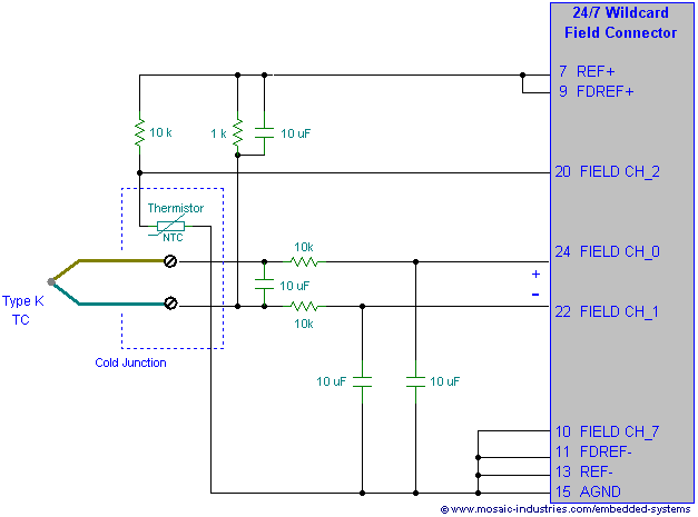
If noise pickup continues to be a problem you can filter the signal just after the cold junction, as shown in the following thermocouple measurement circuit schematic.
Thermocouple measurement circuit schematic

To read the thermocouple, the A/D converter uses buffered mode, allowing greater source resistance. A filter resistance of 10 kΩ is placed in series with each of the thermocouple leads, and large decoupling capacitors are used to minimize any noise pickup which may have occurred on the thermocouple leads. The decoupling capacitors must be low leakage capacitors, preferably ceramic capacitors.
For converting the thermocouple voltage, the A/D is configured for a fully differential, bipolar, buffered conversion on channel pair CH_0_1. Channel 0 is the positive input, and channel 1 the negative input. The cold junction thermistor is converted as before, configuring the A/D for a pseudo-differential conversion on CH_2_7.
Note that in the diagram the negative output of the thermocouple is connected to the reference supply through a 1 kΩ resistor, biasing the common mode voltage of the measurement at 2.5V. The common mode measurement range of the A/D inputs, which is -30 mV to +5.03 V in unbuffered mode, is reduced to +50 mV to +3.5V in buffered mode. Consequently, when using buffered mode we can not bias the thermocouple at ground as we had before, but must bias it within the buffered mode's common mode range. Connecting it to the 2.5V reference provides a convenient fixed voltage guaranteed to be within the common mode range. It is connected through a resistor so that any potential accidental shorts of the thermocouple to ground do not harm the reference supply.
To prevent unbalanced offset errors, both leads of the thermocouple must be filtered identically. A potential disadvantage of using buffered mode is that a small DC offset is added to the input signal. That offset is generated by a 1 nA input offset current from the buffer amplifier through an onboard 2.2 kΩ protection resistor and the external 10kΩ filter resistor that is in series with each of the inputs to the analog to digital converter. That current produces a small input offset voltage on each input of 1nA * 12.2kΩ = 12.2 μV. If only one side of the thermocouple signal were filtered, that offset would correspond to a temperature error of about 0.3°C (for a type K thermocouple). However, if both sides of the thermocouple are filtered identically, the input offsets introduced by the buffer amplifier to the two sides counter balance each other, resulting in no additional error.
See also →
