Prototyping Wildcard User Guide
Easily create custom circuits you can interface to your embedded controller's hardware
The Prototyping Wildcard is a general purpose, sea-of-holes printed circuit board you can use to prototype custom circuitry. This convenient PCB provides power supply rails and several convenient I/O connectors. It may be mounted on any of Mosaic’s Controllers, Docking Panels or PowerDock and derives its power from the Wildcard Bus. You can also operate it stand-alone if you provide power to it. Similar but superior to a breadboard, the Prototyping Wildcard makes development of your instrument easy. It reduces your time to market by allowing you to plug in custom components, and get started with instrumentation immediately. Learn here about its capabilities, how to use it, and connecting to it.
Specifications
| Prototyping Wildcard Specifications | |
|---|---|
| Prototyping Area: | A sea-of-holes of 232 general purpose plated through holes for mounting through-hole components. Holes are arranged in labeled groups for easy identification. |
| Power Rails: | Connected plated through holes are provided for power and ground derived from the WIldcard bus: +5V power - 21 connected holes for regulated +5V power. Power return - 34 connected holes for power ground return. The metalization surrounding the board’s mounting holes is also grounded. V+Raw - 4 connected holes for V+Raw; depending on the power supplied to the attached controller these may provide anywhere between +8 and +26 volts. |
| Wildcard Connector: | A 24-pin stacking go-through header is provided so that the prototyping board may be mounted on Mosaic’s controllers or docking panels. When mounted on a Controller or Docking Panel, Wildcard bus signals may be used, and power for the prototyping board is provided by the Wildcard bus. |
| Right-Angle Field Header: | A 24-pin right-angle header is provided for connection to the field headers of other Wildcards, or for other use. An additional 24 holes are provided that connect to this header for convenience in wiring to the header. |
| Vertical Field Header: | A 24-pin vertical header is provided for user-provided power or I/O signals. An additional 24 holes adjacent to the header and connected to it are provided for convenience in wiring to the header. |
| Weight: | 16 gram |
| Size : | 2" x 2.5" x 0.365"1) (50.8mm x 63.5mm x 9.3mm) |
Mounting the Prototyping Wildcard
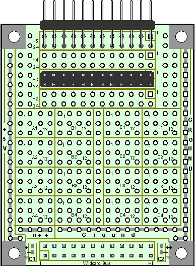
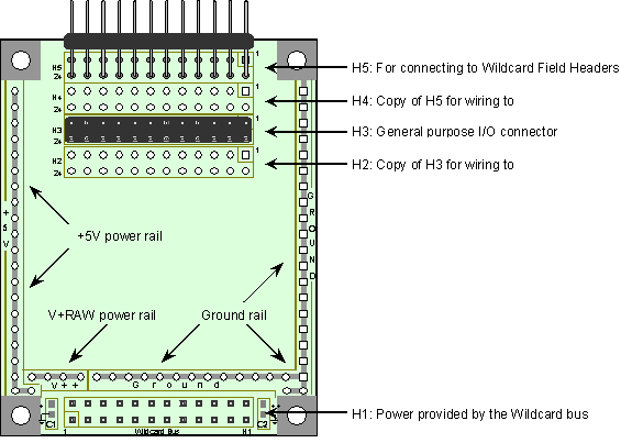
The prototyping card may be used as a stand-alone board or it may be mounted on any of Mosaic’s controllers. To mount it on a Controller, Docking Panel, or Power Dock simply plug it into Wildcard port 0 or 1. It passes the Wildcard bus through its Wildcard connector so that other Wildcards may be stacked either above or below it. It does not take a Wildcard address, so it does not decrease the total number of other Wildcards that may be stacked together. Figure 1 shows the board and Figure 2 points out its functional areas.
Prototyping Area
Most of the board’s area contains plated through holes for mounting your custom electronic components. You may solder components to the holes or wire from hole to hole. To make it easy to locate holes as you turn the board over, most of the holes are arranged in rectangles containing 12 holes each. Each rectangle is labeled on both sides of the board (as A1, A2, A3, A4, B1, B2, … D3, D4), and the holes within each rectangle are numbered 1 through 12, with labels for holes 1 and 12 also on both sides of the board.
Power and Ground Rails
Along the edges of the board there are strips of prewired holes for power and ground. A +5 volt power rail lines one side of the board, and ground on the other side. There are also four connected holes that provide unregulated V+Raw. The +5 volt power, V+Raw, and Ground are all derived from the Wildcard connector. If you choose not to mount the board on a Wildcard bus you may wire your own supply to these rails.
A 1 μF ceramic capacitor is provided on the V+RAW line, and 1 μF and 10 μF ceramic capacitors are provided to filter the already regulated +5 V power rail. If you use digital logic on the board with large transient current requirements, you may need to mount additional bypass and filter capacitors.
Figure 1. Top view of the Prototyping Wildcard showing prototyping area, power rails, and connectors.
Right-Angle Field Header, H5, and Connecting Holes, H4
A right-angle field header makes it easy to cable to other Wildcards using standard 24-pin IDC ribbon cables and sockets. You may use this header as needed for other purposes too. To make it easy to wire to, a separate sea of 24 holes, labeled H4, is provided. The holes of H4 are already connected one-for-one to the 24 pins of H5.
Vertical I/O Header, H3, and Connecting Holes, H2
A vertical 24-pin header is provided for connecting to other devices using standard 24-pin IDC ribbon cables and sockets. You may use this header for whatever you need. To make it easy to wire to this header a separate sea of 24 holes, labeled H2, is provided. These holes of H2 are wired one-for-one to the 24 pins of H3.
Figure 2. Top view of the Prototyping Wildcard highlighting its I/O connectors and power supply rails.
Wildcard Bus Connector, H1
The pin-out of the Wildcard bus connector is shown in the following Table. Other than for pins 1, 2, and 4 (for Ground, +5V, and V+RAW) which are run to the power supply rails, you would not generally need access to the signals on this connector. Even so, the pin-out of the Table is provided for sophisticated users who may need one of the signals.
Wildcard Bus Connector
| H3 Wildcard Bus | |||
|---|---|---|---|
| Signal | Pins | Signal | |
| GND | – 1 | 2 – | +5V |
| /IRQ | – 3 | 4 – | V+RAW |
| PG1 | – 5 | 6 – | PG0 |
| MOSI | – 7 | 8 – | MISO |
| /RESET | – 9 | 10 – | SCK |
| /MOD.CS | – 11 | 12 – | 16 MHz |
| E Clock | – 13 | 14 – | R/W |
| /OE | – 15 | 16 – | /WE |
| AD7 | – 17 | 18 – | AD6 |
| AD5 | – 19 | 20 – | AD4 |
| AD3 | – 21 | 22 – | AD2 |
| AD1 | – 23 | 24 – | AD0 |
See also → Prototyping Wildcard
Compatible Controllers


