Customizing Your Conductivity Sensing Circuit
You can change operating frequency, bandwidth, or conductivity range
There are number of potential customizations of a stand-alone version of the Conductivity Sensing Wildcard to make it better suited to your application. In particular, you can change the values of specific components (by soldering others in their place) to vary the operation of the circuit.
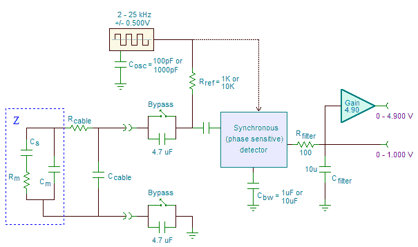
The following figure highlights the board's components that can be changed:
We'll discuss the circuit function of the components you may want to change, then point out where on the board you can find these components.
Replacing components
Shifting the measurement range with the reference resistor
The most likely customization you might make is to change the midpoint of the measurement range. For each measurement channel the measurement scale is set with a single reference resistor, Rref in the above figure.
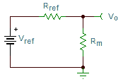
In the above circuit the reference resistor and the resistance of the conductive medium being measured together act as a voltage divider. Neglecting for the moment the other components in the circuit, the two resistors produce the output voltage as shown in the following figure:
The output voltage, Vo, is roughly given by,
where Rref is the reference resistor on the board and Rm is the resistance (the inverse of the conductance) of the media being probed.
The output is one half of full scale when Rm = Rref ; consequently, you can use Rref to set the center of the measurement range. How far from the center you can accurately measure depends on the accuracy with which you are able to measure the output voltage. When the board is used in conjunction with Mosaic's Analog I/O Wildcard, the output is measured with 16-bit precision and high accuracy. In that case resistances can be ascertained to better than a factor of one hundred on each side of the center set by Rref.
The useful measurement range you achieve depends on the accuracy and precision of the voltmeter you use to measure the output. For example, to attain a worst case accuracy of about ± 10% of the measured value, if your meter is accurate to ± 5 mV, you could measure from 0.05V to 0.95V, corresponding to Rm from Rref /20 to 20·Rref. If your meter is accurate to ± 1 mV, then the range would increase to Rref/100 to 100·Rref.
In its default configuration the board ships with Rref = 10 KΩ, corresponding to a midpoint of 0.1 mS (that is, 0.1 milli-Siemen or 100 μS (micro-Siemens)), given a conductivity cell with K=1. You can measure accurately to a factor of 20x above and below that value. You could change the midpoint if you like to 1 KΩ, corresponding to a mid-range conductivity of 1000 μS, as summarized in the following table:
| Measurement Range Corresponding to Rref (assuming a cell constant of K=1 and a max error of 10% of value) | ||
|---|---|---|
| Rref | ||
| 10 KΩ | 1 KΩ | |
| Midpoint resistance | 10 KΩ | 1 KΩ |
| Midpoint conductance | 100 μS | 1 mS |
| Conductance range (Vo measured with ± 5 mV resolution)1) | 5 μS – 2 mS | 50 μS – 20 mS |
| Conductance range (Vo measured with ± 1 mV resolution)2) | 1 μS – 10 mS | 10 μS – 100 mS |
The board has been tested with Rref values of both 1 KΩ and 10 KΩ, and works well over that range. There may be problems that arise when using Rref values that deviate from that range. Values significantly lower than 1 KΩ may load internal circuitry causing crosstalk between channels. Values much greater than 10 KΩ will cause the results to be more susceptible to cable capacitance, making it more difficult to calibrate away.
Changing the measurement frequency
The measurement excitation frequency is set with a capacitor to a default of approximately 25 kHz by an onboard capacitor, shown in the above figure as Cosc. You can solder another capacitor across that one to lower the frequency, to whatever you want, say 2 kHz or 200 Hz. Or you can replace the capacitor for a greater frequency, which may be useful for conductivity electrodes of small surface area.
The primary consideration in choosing the measurement frequency is that it be great enough that the conductivity electrodes' interfacial capacitance impedance be small. That capacitive impedance is in series with the resistance/conductance being measured. The circuit is able to remove its influence on the measurement when it is small enough, but at low operating frequencies and small interfacial capacitance, the capacitive impedance becomes great enough that it causes errors. The default frequency of 25 kHz is usually sufficient to work with most conductivity electrodes.
Well made conductivity probes take care to enhance the electrode's microscopic surface area by using activated carbon or high surface area platinum oxide. In that case a low frequency may be used effectively. There's an advantage to using a low frequency if long cables are needed, as low frequency operation is less influenced by cable capacitance.
Using a custom probe without a very high surface area calls for a greater operating frequency. However there is a trade-off in going to greater frequencies as cable capacitance becomes more influential. Ideally, you should minimize cable length and capacitance.
The frequency of oscillation depends on Cosc roughly as,
The following table provides approximate operating frequency as a function of the value of Cosc.
| Cosc | Frequency (kHz) |
|---|---|
| 0 pF | 190 kHz |
| 100 pF | 37 kHz |
| 1000 pF | 4.4 kHz |
| 0.01 μF | 400 Hz3) |
These frequencies depend on a process-dependent internal capacitance in an IC, and so are only roughly accurate. To determine the actual frequency you should always rely on actual measurements. You can measure the frequency by placing an oscilloscope lead on pin 3 of H4 and inspecting the square wave there.
Changing the detection bandwidth
A phase sensitive detector on the board demodulates the AC signal from the voltage divider and produces an output proportional to the real (i.e., resistive) part of the the complex impedance of the conductivity probe. The bandwidth of the detection process is set by a capacitor, CBW, for each channel. The response time of the detection method is inversely proportional to the bandwidth, and there is a trade-off between response time and output ripple, summarized in the following equations:
Ripple ≈ 1/(Fosc·Tresponse)
The response time depends on the combined parallel resistance of the reference resistor and the measured resistance (conductance) multiplied by the bandwidth capacitor plus 1 μF. The ripple voltage is very small for slow response times, but becomes greater if the response time is sped up.
For most applications It is unlikely that you would need to change the value of the bandwidth capacitor. However, for measuring rapid changes in fluid conductance you may want a quicker response time.
Changing the output filtering time
Referring again to the above circuit, two components, Rfilter and Cfilter, add an additional low pass filter with a default time constant of 1 msec, corresponding to a cut-off frequency of 159 Hz. There are only two reasons for ever changing these components. First, if you require a greater or lesser filter time, perhaps to obtain less ripple or faster responsiveness, you may change the value of Cfilter. Secondly, if you are unable to measure the output voltage with a high impedance meter the series resistance, Rfilter, may introduce a small error. In that case you can replace Rfilter with a zero ohm short. If you do, you will need to remove Cfilter from the board so that it does not destabilize the output op-amp. If you can not measure the primary output with a high impedance meter, instead of changing Rfilter it is better to measure instead the amplified secondary output, OUT1_HI or OUT2_HI. That amplified output ranges from 0 to 4.90V instead of 0 to 1.00V, and it is provided directly by a low impedance op-amp output so it won't be distorted if your measuring device is a low impedance.
Bypassing the isolation capacitors
As provided, the board includes isolation capacitors to provide galvanic isolation between the measurement circuitry and the media being measured. These are provided to limit current in the event the media being measured in inadequately isolated from other voltage sources. In particular, it may not be connected to other devices (stirring motors or pumps for example) that provide a leakage path to AC mains voltage. In that case the isolation capacitors offer some protection. However, their series capacitance and ESR introduce a small error when measuring extremely high conductances. You can remove their effects by shorting them with bypass zero ohm shorts. There are pads on the board for soldering zero ohm resistors or wire shorts.
Minimizing the influence of cable capacitance
Cable capacitance, shown in the figure above as Ccable, should be minimized by using the shortest, lowest capacitance cables available. Cable capacitance provides a current leakage path around the conductance sensor, complicating the measurement of very low conductance. Although its influence is mitigated by the phase sensitive detection method and by calibration, it is best to minimize the capacitance if at all possible.
Component placement
You can find the components discussed in the above by examining the board. Each component is labeled with a designator. The following table lists the appropriate designators:
| Component | Function | Designators Channel 1 \ Channel 2 |
|---|---|---|
| Rref | Sets measurement range | R12 / R3 |
| COSC | Sets frequency | C37 |
| CBW | Controls detection bandwidth | C20 / C19 |
| Cfilter | Output noise filter | C23 / C31 |
| Rfilter | Output noise filter | R17 / R21 |
| High-side bypass | Bypasses isolation capacitor | R11 / R2 |
| Low-side bypass | Bypasses isolation capacitor | R6 / R19 |
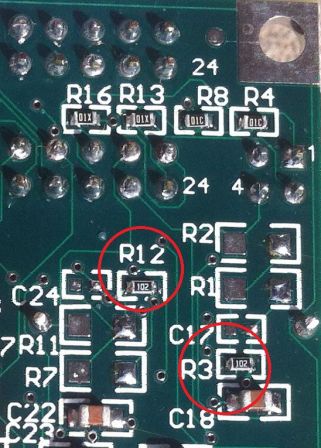
The following photo points out the location of the reference resistors for both channels, R12 for channel 1 and R3 for channel 2.
The values show on this board for the reference resistors is 1 KΩ (the "102" markings indicates a value of 10 followed by two more zeros, or 1000 ohms).


