

|
|
Table of ContentsConnecting To Mosaic Controller RS422/485 Configuration Jumpers Protocol Configuration and Direction Control Registers Overview of the Software Device Driver Functions Installing the UART Module Driver Software Using the Driver Code with Forth UART Direction Control in a Multitasking System C Demonstration Program (in pdf) |
UART Wildcard User GuideProtocol Configuration and Direction Control RegistersAside from the RS485 and termination network jumpers described above, all remaining protocol selections are performed under software control by writing to control registers implemented by logic on the Wildcard. It is not necessary to understand this implementation detail, as the pre-coded functions described in the Glossary transparently manage these registers for you. This information is presented for those who want to know how the low level hardware works. The programmable logic chip on the UART Wildcard implements four registers named CONFIG1, CONFIG2, DIRECTION1, and DIRECTION2. They are addressed sequentially starting at offset 0x10 in the Wildcard’s address space. The CONFIG registers configure the associated serial channel’s protocol. The DIRECTION registers are used to control the direction of the RS422/485 driver chips by enabling and disabling the channel’s receiver and transmitter. Table 1-2 describes the contents of these registers. The D4 through D0 labels at the top of the table designate the data bits that access the information in the register. Table 1-2 Protocol and Direction Control Registers 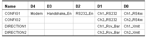
CONFIG1 and CONFIG2 configure the protocols for serial Channel1 and Channel2, respectively. In both configuration registers, D1 is set true in RS232 mode and false otherwise, and D0 (labeled RS4xx) is set true in RS422 or RS485 mode, and false otherwise. Recall that RS422 and RS485 share a driver/receiver chip. These bits determine which input receiver drives the serial input pin on the UART chip for the specified channel. When set, the RS232_En bit in CONFIG1 powers up the serial driver chip that handles the transmit and receive signals for Channels 1 and 2. When set, the Handshake_En bit powers up the serial driver chip that handles the modem handshaking signals for Channel1. The Modem bit is set to true if the optional modem handshaking signals are in use. When set, this bit causes the hardware to route the incoming signal from the RxD2/DCD1 pin on the field header to the /DCD1 pin on the UART. Handling of the modem signals is described in more detail in the next section. The DIRECTION1 and DIRECTION2 registers control the transmitter and receiver enable signals for the RS422/RS485 driver/receiver chips for Channels 1 and 2, respectively. The Ch1_Xmit and Ch2_Xmit turn the respective transmitters on when the bit is set, and the active low Ch1_Rcv_Bar and Ch2_Rcv_Bar signals turn the respective receivers on when the bit is clear. In RS422 mode, both the driver and the receiver are enabled, thereby enabling full duplex communications. In RS485 mode, the driver is off and the receiver is on in receive mode, and the driver is on and the receiver is off in transmit mode. The configuration and direction registers are transparently managed by the functions described in the Glossary below. |
Home|Site Map|Products|Manuals|Resources|Order|About Us
Copyright (c) 2006 Mosaic Industries, Inc.
Your source for single board computers, embedded controllers, and operator interfaces for instruments and automation