Loading

|
|
Loading
|
|
|
|
|
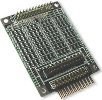
Mosaic embedded designs » Embedded controllers » Expansion I/O modules » Analog filter prototyping board The I/O Filter Wildcard™
|
| A) | Often voltage attenuation may be needed for A/D measurement as shown in Figure 3A. Resistive dividers are produced simply by inserting through-hole resistors at locations nA and nC for circuit n. |
| B) |
RC filters are very useful as anti-aliasing filters when using the Analog I/O Wildcard. Figure 3B shows the most simple of these. |
| C) | Sometimes an input signal should float to an intermediate voltage between power and ground, or it should be shifted as well as attenuated, as shown in the circuit of Figure 3C. |
| D) | If an input exceeds the voltage levels allowed by your controller or Wildcard, you can clamp the input to the power supply rails using Schottkey diodes as show in Figure 3D. |
| E) | The I/O Filter Wildcard can also serve as a general purpose prototyping board. Figure 3E shows the creation of a 2.5V reference on I/O pin 5 using a precision voltage reference chip and the 5V supply. |
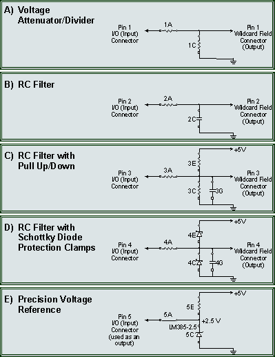
Several of the many input/output filters and other circuits that can easily be configured.
Home | Site Map | Products | Documentation | Resources | Order | About Us
Copyright © 2014 Mosaic Industries, Inc.
Your source for single board computers, embedded controllers, and operator interfaces for instruments and automation
Prototyping Board | Analog Filter | Analog Digital Conversion | Signal Conditioning | A/D Measurements