

|
|
Table of ContentsConnecting to the 24/7 Data Acquisition Module Converter Noise and Effective Resolution Other Sources of Noise and Offset Error Tips For Measuring Small Voltages Addressing the 24/7 WildCard Using Module Select Jumpers Initializing the 24/7 Data Acquisition Wildcard Specifying the Reference Voltage Calibration Options Single- and Multi-Channel Sampling Continuous Sampling from a Single Channel |
24/7 Data Acquisition Wildcard Users Guide| Next>> IntroductionThe 24/7 Data Acquisition Wildcard gives you the ability to amplify and sample low level signals at various conversion rates directly from transducers using a sigma-delta technique. Its state-of-the-art analog-to-digital converter, Analog Devices� AD7714, provides 24 bits of resolution with no missing codes performance. The 24/7 Data Acquisition Wildcard performs all signal conditioning and conversion for a system of up to seven input channels that are configurable in 10 different ways. This Wildcard also provides three general purpose digital inputs. Specifications are summarized in the following table.
High-level software routines allow you to initialize, calibrate, configure, and control the 24/7 Data Acquisition Module. Once commanded to start converting, the analog to digital converter continually samples and converts at a fixed rate. You can read the output once, or store each sequential conversion to a memory buffer. You must sample one channel at a time; changing channels requires restarting the conversion process with a different channel specified. 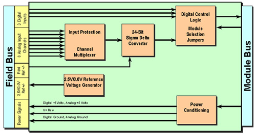
The above figure diagrams the WildCard. Signals are taken from the Field Bus on the left. The eight inputs may be configured in four pairs, for four differential input channels, or they may be configured as seven pseudo-differential inputs with the eighth line acting as a common return. Power and reference voltages are provided to the field header for your use. You can configure the converter to use the 2.5 volt internal reference, or to take its reference from the field header. Many sensors and measurement methods produce an output that is ratiometric; that is, an output proportional to a reference signal or that is accompanied by its own full scale reference signal. You can accurately measure these by providing an appropriate reference voltage to the reference inputs on the field header. Communication with the WildCard is via the SPI serial lines and is handled transparently by the supplied driver routines. This document describes, step by step, how to use the 24/7 Data Acquisition Module. It will show you how to:
| Next>> | ||||||||||||||||||||||||||||||||||||||||||||||||||||||||||||||||
Home|Site Map|Products|Manuals|Resources|Order|About Us
Copyright (c) 2006 Mosaic Industries, Inc.
Your source for single board computers, embedded controllers, and operator interfaces for instruments and automation