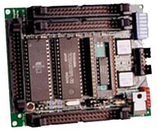
The QED Board is a legacy product not available for new customers. If you're looking
for a HC11-based single-board computer programmable in C or Forth, consider Mosaic's
QCard™ Controller. For a faster and more powerful platform with the same
compatibility with our all of our Wildcard™ Modular I/O Boards,
consider the PDQ Board™.
For existing customers looking for QED Board documentation, see a summary of
specifications below, or download
full documentation PDF files here.
Processor's address space is expanded to 8 Megabytes.
Digital Input and Output
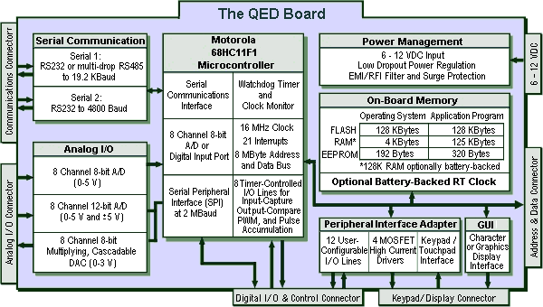
The 68HC11F1 processor provides 16 digital I/O lines. Additionally, an
onboard peripheral interface adaptor provides three 8 bit I/O ports named
Peripheral Ports A, B, and C. Of these 40 user-configurable lines, 28 are
uncommitted and the remainder implement high-current driver outputs and the
keypad/touchscreen interface.
Onboard Memory
96K minimum up to 512K maximum.
320 bytes of EEPROM are available for the user.
There are 3 memory sockets on the board:
Socket 1 accommodates 256K Flash.
Socket 2 accommodates a 32K or 128K SRAM with optional battery backup. 128K SRAM is standard.
Socket 3 is available to accommodate the optional battery-backed real-time clock.
High Current Drivers
Four open-drain MOSFET drivers are brought out to the keypad/display
connector. Each driver can sink up to 150 mA continuously, and up to 1 amp on an
intermittent basis. Onboard snubber diodes allow control of inductive loads.
Real-Time Clock
An optional real-time clock socket can be installed under the 32K RAM in
memory socket 2. It battery backs the RAM and is fully supported by onboard
software.
Timer Controlled Input and Output
3 or 4 input capture functions facilitate accurate detection of pulse edges
and measurement of pulse widths.
4 or 5 output compare functions make it easy to create complex waveforms and
pulse-width modulated signals.
A pulse accumulator facilitates frequency measurement and pulse counting.
Keypad and Touchscreen Interface
A twenty button (4 x 5) keypad connects via a direct cable interface and is
read by a pre-coded keypad scanning routine.
A touchscreen overlay is available with the graphics display.
Analog to Digital Conversion
8 channels of 8 bit A/D conversion with up to 100 kHz sampling frequency.
8 channels single-ended or 4 channels differential 12 bit A/D conversion with
up to 30 kHz sampling frequency. Unipolar (0 to 5V input) and bipolar (-5 to 5V
input) conversions are supported.
Display Interface
An LCD display connects via a direct cable and is controlled by pre-coded
driver routines. The interface supports:
Alphanumeric displays of up to 4 lines by 20 characters, or
A 128 x 240 pixel graphics display with a 2.5" by 4.5" viewing area that
displays 16 lines of text with 40 characters per line.
Digital to Analog Conversion
8 channels of 8 bit multiplying digital-to-analog conversion.
Pairs of D/A converters may be combined to yield higher resolution (11+ bits)
D/A conversion.
Communications
A hardware UART supports either RS232 or RS485 at up to 19.2 Kbaud. The RS232
transmitter can be tri-stated to implement full-duplex multidrop communications.
A second software UART implements an RS232 interface at up to 4800 baud.
A fast synchronous serial peripheral interface (SPI) provides communications
at speeds up to 2 megabaud.
The onboard D/A converter and 12 bit A/D are controlled via the SPI.
Power
75 mA average current consumption at +5 volts.
Onboard regulation converts 6-12VDC into a +5V regulated 750 mA primary supply
as well as a 10 mA secondary supply used by onboard analog circuitry.
A digital shutdown signal can turn off the primary supply, reducing power
consumption to 30 mW.
The board can be directly powered by a regulated +5V supply.
A power monitor ensures orderly power up/power down.
A power fail early warning signal is generated onboard.
An EMI filter and a power surge protector are on the board.
Runtime Security
A watchdog timer and clock monitor ensure orderly reset if a processor error
occurs.
Connectors
All connectors use standard shrouded single or dual row .025" square posts on
a 0.1" centerline pitch.
40 pin digital I/O and control bus, dual row.
40 pin analog I/O bus, dual row.
40 pin address/data bus, dual row.
34 pin interface connector (keypad and display), dual row.
10 pin serial communications connector, dual row.
6 pin power connector, single row.
Interrupts
21 interrupts support the 68HC11's on-chip subsystems.
Size and Weight
3.2" x 4.0" surface-mount board weighs 3.5 oz (100 g).