

|
|
Table of ContentsConnecting To Mosaic Controller Selecting the Digital I/O Wildcard Address Current Capability of the Digital Output Lines Protecting the Input and Output Pins Connecting to the Field Header Setting the Direction of the I/O Lines C Code to initialize the Digital I/O Wildcard Forth Code to initialize the Digital I/O Wildcard C Code to control the Digital I/O Wildcard
Forth Code to control the Digital I/O Wildcard
|
Digital I/O Wildcard User GuideProtecting the Input and Output PinsThese output pins are very useful because they can directly drive a wide range of devices. Nevertheless, any circuitry connected to them should take care to:
We’ll address each of these concerns in turn. Preventing Excessive Voltages: Excessive voltages are prevented by ensuring that voltages of less than a diode drop below ground (-0.5 V) or greater than a diode drop above 5V (5.5 V ) are never applied to an output pin. For some applications, particularly when driving inductive loads such as relays, you may need to provide Schottkey diode clamps between the pin and +5V and between the pin and ground. If an output pin is directly connected to a voltage source below ground or above 5V the Wildcard will be destroyed. Whenever possible, it’s a good idea to drive external devices through a current limiting resistor (say 100 Ω). Preventing Excessive Currents: The current into or out of any output pin on the Wildcard should also be limited to prevent damage. These pins can withstand brief source or sink currents of up to 100 mA at room temperature, but you should never allow currents greater than 100 mA. Load circuitry that requires significant current to be sourced or sunk by the digital output should include external resistors to ensure that an absolute maximum rating of 100 mA on a single output pin is never exceeded. Preventing Excessive Power: Never cause more than 250 mW of I/O pin power to be dissipated on the Wildcard. The total power allowed is the sum of the power dissipated by each pin. For output highs that power is the product of the source current and the difference between +5V and VOH. For output lows that power is the product of the sinked current and VOL. A limitation of the total power to 250 mW is actually quite generous. Note that from the above figure, when 25 mA is sunk into an output low the power contributed is only 7.5 mW (for a typical device, max of 12.5 mW for any device). Consequently, you can continuously sink 25 mA into all the output pins simultaneously. Connecting to the Field HeaderAll connections to the Wildcard should be made throught the Field Header, H2. This right-angle header provides the 20 I/O lines as well as power and ground connections. Table 1-3: Digital I/O Field Header H2 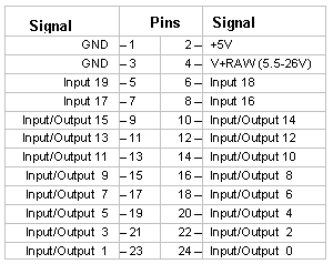 |
Home|Site Map|Products|Manuals|Resources|Order|About Us
Copyright (c) 2006 Mosaic Industries, Inc.
Your source for single board computers, embedded controllers, and operator interfaces for instruments and automation