

|
|
Table of ContentsConnecting To Mosaic Controller Selecting the Wildcard Address Selecting the Reference Voltage Analog I/O Wildcard Field Header Overview of the Software Device Driver Functions Initializing the Analog I/O Software Drivers Installing the Analog I/O Wildcard Driver Software |
Analog I/O Wildcard User GuideConnecting To the Wildcard Bus on the Controller BoardTo connect the Analog I/O Wildcard to the Wildcard bus on the controller board, follow these simple steps: With the power off, connect the female 24-pin side of the stacking go-through Wildcard bus header on the bottom of the Analog I/O Wildcard to Wildcard Port 0 or Wildcard Port 1 on the Wildcard bus on the controller board. The corner mounting holes on the module should line up with the standoffs on the controller board. The module ports are labeled on the silkscreen of the controller board. Note that the Analog I/O Wildcard headers are configured to allow direct stacking onto the Wildcard bus, even if other Wildcards are also in-stalled. Do not use ribbon cables to connect the Analog I/O Wildcard to the Wildcard bus. Use of ribbon cables on the Analog I/O Wildcard’s field header is fine. CAUTION: The Wildcard bus does not have keyed connectors. Be sure to insert the module so that all pins are connected. The Wildcard bus and the Analog I/O Wildcard can be permanently damaged if the connection is done incorrectly. Selecting the Wildcard AddressOnce you have connected the Analog I/O Wildcard to the Wildcard bus, you must set the address of the mod-ule using jumper shunts across J1 and J2. The Wildcard Select Jumpers, labeled J1 and J2, select a 2-bit code that sets a unique address on the Wildcard port of the Mosaic controller. Each Wildcard port on the Mosaic controller accommodates up to 4 Wildcards. Wildcard Port 0 provides access to modules 0-3 while Wildcard Port 1 provides access to modules 4-7. Two Wildcards on the same port cannot have the same address (jumper settings). Table 1-2 shows the possible jumper settings and the corresponding addresses. Table 1-2 Jumper Settings and Associated Addresses 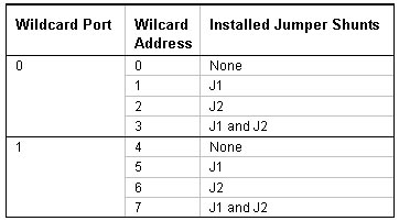 |
Home|Site Map|Products|Manuals|Resources|Order|About Us
Copyright (c) 2006 Mosaic Industries, Inc.
Your source for single board computers, embedded controllers, and operator interfaces for instruments and automation