|
|
|
Input Channels
|
4
unipolar single-ended; pairs of channels may be used for differential input
|
|
Resolution
|
16-bits (
0 – 65,535 counts)
|
|
Input Voltage Range
|
0 to
10.24 V is converted to 0-2.048 V presented to the Analog I/O Wildcard
(range customizable by component substitution)
|
|
Input Filtering
|
Single-pole
265 Hz low-pass filter, reconfigurable by component substitution
|
|
Input
Impedance
|
376 KΩ
|
|
Offset
and Scale Errors
|
±0.1% of FS offset error and
±1-2% of FS gain error are added to any A/D offset and gain errors
|
|
|
|
|
|
|
Output
Channels
|
4 unipolar single-ended
|
|
Resolution
|
12-bits ( 0 – 4095 counts)
|
|
Full
Scale
Output Voltage
|
0 to 10.24 V is produced from
0-4.096 V provided by the Analog I/O Wildcard
(range customizable by component substitution)
|
|
Settling
Time
|
300 msec typically, slew rate is 0.1V/msec
|
|
Allowed
Load Resistance
|
³
1KΩ, Op-amp output sources and sinks up to 10 mA, sink current limited
at Vo=0 by 39Ω output resistance.
|
|
Offset
and Scale Errors
|
±0.05% of FS offset error and
±1-2% of FS gain error are added to any A/D offset and gain errors
|
|
|
|
|
|
|
Input Channels
|
4
unipolar single-ended current sinks
|
|
Resolution
|
16-bits (
0 – 65,535 counts)
|
|
Input Current Range
|
0 to 20.48
mA is converted to 0–2.048 V presented to the Analog I/O Wildcard
(range customizable by component substitution)
|
|
Input Protection
|
Protected
to -30V, +15V, or +100 mA steady state input
|
|
Input
Resistance
|
200 Ω (for up to 50 mA
input, dynamic resistance drops toward 100 Ω for greater currents)
|
|
Offset
and Scale Errors
|
No offset error and ±1% of FS
gain error is added to any A/D offset and gain errors
|
|
|
|
|
|
|
Output Channels
|
4 unipolar single-ended current
sources
|
|
Resolution
|
12-bits ( 0 – 4095 counts)
|
|
Output Current Range
|
0 to 20.48 mA is produced from
0–4.096 V provided by the Analog I/O Wildcard
(range customizable by component substitution)
|
|
Output Compliance
|
Up to 10V
|
|
Allowed
Load Resistance
|
Any resistance £ 500Ω
|
|
Offset
and Scale Errors
|
±0.04 mA offset error, ±0.05
mA/V compliance error, and ±1% typ gain error added to DAC offset and gain
errors.
|


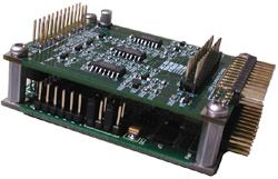 The Signal Conditioning Wildcard is used with the Analog
I/O Wildcard to increase its input and output voltage range and to add 4-20 mA current
input and output capability This document describes the capabilities of the
Signal Conditioning Wildcard and tells how to connect and use it with an Analog
I/O Wildcard.
The Signal Conditioning Wildcard is used with the Analog
I/O Wildcard to increase its input and output voltage range and to add 4-20 mA current
input and output capability This document describes the capabilities of the
Signal Conditioning Wildcard and tells how to connect and use it with an Analog
I/O Wildcard.