

|
|
Table of ContentsPlugging in the Power I/O Wildcard Setting Outputs and Reading Inputs Connecting High-Current Loads to the Outputs Maximum Ratings: Current, Power and Switching Frequency |
Power I/O Wildcard User GuideHeat SinkingWhile it is possible to heat sink the MOSFETS, because of the limited space between MOSFETs and the need to electrically insulate the heat sink from each MOSFET we do not recommend heat sinking. Even so, if you are careful and you do heat sink the MOSFET drivers the maximum ratings improve. In particular, one or two of the channels can be heat sunk with small free-standing TO-220 heat sinks. To determine the maximum ratings, the same equation may be used, but with the appropriate thermal resistance substituted for RΘ. To the heat sink thermal resistance (heat sink to ambient) you must always add the thermal resistance between the junction and the package of 3.5 °C/W, and the case to sink resistance, typically between 0.1 and 1.0 °C/W. Small, free-standing heat sinks (0.5 x0.5 x0.75" heatsinks of 18.8 °C/W such as Digikey HS121-ND) can be used to decrease the thermal resistance from 62 to about 18.8+3.5+1.0 = 23.3 °C/W resulting in an increase in continuous current from 2A to 3.3A. The tabs of the TO-220 packages of the MOSFETs are not electrically isolated − they are connected to the drains (the outputs). Consequently, if the package is heat sunk the heat sink must be kept electrically insulated from the tabs, or it must be kept insulated from everything else. Connecting to the InputsThe high voltage inputs are also optically isolated to ±2500 volts and capable of sensing voltages of ±4 to ±50 VDC. Figure 1-2 illustrates how to connect an input voltage to the Power I/O Wildcard. When the input voltage is ±5 to ±50V, a logical 1 input will be read. When the input voltage is less than ±0.8V, a logical 0 input will be read. 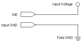
Onboard pull-up resistors (labeled PU0 to PU3 on the Power I/O Wildcard silkscreen) allow you to monitor the state of a contact closure device such as a switch. The switch is connected as shown in Figure 1-3. For example, to interface a contact closure device to input channel IN1, install a jumper shunt across J5 and connect the contact closure device. The input is read as a logical 1 when the switch contact is open (contacts not connected), and it is read as a logical 0 when the device is closed (contacts connected). When the pull-up resistors are used, V+ Field IN must be in the range of ±4 to ±50VDC for proper operation. 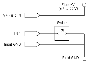
|
Home|Site Map|Products|Manuals|Resources|Order|About Us
Copyright (c) 2006 Mosaic Industries, Inc.
Your source for single board computers, embedded controllers, and operator interfaces for instruments and automation