|
|
The C Programmer’s Guide to the Mosaic HandheldTable of ContentsPART 1 GETTING STARTED Introduction. How to Use This Manual Chapter 1: Getting to Know Your Handheld Instrument Chapter 2: Powering Your Handheld PART 2 PROGRAMMING THE MOSAIC HANDHELD Chapter 4: The IDE: Writing, Compiling, Downloading and Debugging Programs Chapter 5: Making Effective Use of Memory Chapter 6: Real Time Programming Chapter 7: Failure and Run-Time Error Recovery Chapter 8: Programming the Graphical User Interface The Structure Of The GUI Toolkit Transferring Your Images to the Handheld Controller Expanding the GUI Toolkit’s Objects and Methods Customizing the Keypad Overlay PART 3 COMMUNICATIONS, MEASUREMENT, AND CONTROL Chapter 9: Digital and Timer-Controlled I/O Chapter 11: Serial Communications Chapter 12: The Battery-Backed Real Time Clock Chapter 13: Customizing the Handheld's I/O PART 4: REFERENCE DATA |
Chapter 8 (continued) GUI Objects in DetailThere are many kinds of GUI objects. Some are tied tightly to particular hardware (the GUI_BATTERY and GUI_DISPLAY), some collect other objects together (GUI Screens), some respond to events (controls), some are tools (the GUI_PEN), and some simply contain data for display (graphics and textboxes). Several of the GUI objects are created and configured when Initialize_GUI is called. These objects include the GUI_DISPLAY, GUI_BATTERY, GUI_BUZZER, GUI_FONT, GUI Screens, GUI Keypads, and GUI_PEN. You can not create more of these object types. For other object such as graphics, textboxes, keys, screens, and plots, you can create as many as you like. All of the GUI Toolkit objects, their 32-bit properties, associated methods, and possible errors are described below. More detailed descriptions of each method, property, and value is available in the GUI Toolkit Glossary. GUI_TOOLKITThe GUI Toolkit is itself an object that contains properties that effect all other objects. The GUI Toolkit Object is called GUI_TOOLKIT. These are its properties, methods, and possible errors: PropertiesTable 8‑2 Properties of the GUI_TOOLKIT.
MethodsTable 8‑3 Methods of the GUI_TOOLKIT.
ErrorsTable 8‑4 Errors of the GUI_TOOLKIT.
GUI_DISPLAYThe GUI_DISPLAY corresponds to the physical display. Properties of the GUI_DISPLAY and all other GUI objects are accessed or modified using the GUI_TOOLKIT methods Set_Property and Get_Property. PropertiesTable 8‑5 Properties of the GUI_DISPLAY.
GUI ScreensA screen is a collection of functionally related objects, including textboxes, plots, and graphics that are presented together on the display. Screens are fixed in size to 128 pixels wide by 128 pixels tall. For speed, objects loaded into screens are aligned on 8 pixel horizontal grid. A property of the GUI Toolkit, called VERTICAL_SNAP_TO_GRID, allows you to align objects vertically as well. The coordinate system for specifying the location of objects and drawing to a screen is in pixels and the origin is the upper left corner of a screen. The x coordinate represents a displacement from the origin in the horizontal direction and the y coordinate represents a displacement from the origin in the vertical direction. An increase in x moves the coordinate to the right and an increase in y moves the coordinate down. Screens whose object images are stored in the display’s memory are called GUI Screens. GUI screens have a visible property that when set, causes the selected screen to be shown on the display and makes all other GUI Screens invisible. Only one GUI Screen can be made visible at a time. GUI Screens are the only objects that are shown on the physical display. To show an object like a graphic on the display, the object must first be loaded into a GUI Screen. The visible screen after Initialize_GUI is called is GUI_SCREEN0. You can also create additional screens that reside in the heap. Heap screens, unlike GUI Screens, can not be made visible. Heap screens allow you to build many different screens when you are initializing your application and then quickly switch them into GUI Screens at run time using the Copy_Screen method. Heap screens are described in detail in a later section. PropertiesTable 8‑6 Properties of GUI Screens.
MethodsTable 8‑7 Methods of GUI Screens.
ErrorsTable 8‑8 Errors of GUI Screens.
GUI KeypadsEach GUI Screen has a corresponding keypad that holds the keys that animate the screen. GUI_SCREEN0 is associated with GUI_KEYPAD0, GUI_SCREEN1 is associated with GUI_KEYPAD1, GUI_SCREEN2 is associated with GUI_KEYPAD2, and GUI_SCREEN3 is associated with GUI_KEYPAD3. GUI Keypads can contain three different types of keys - action keys, data entry keys, and shift keys. Each type of key is covered in a later section. Only the keypad of the visible screen is active (i.e. responds to key presses). PropertiesTable 8‑9 Properties of the GUI Keypads.
MethodsTable 8‑10 Methods of the GUI Keypads.
ErrorsTable 8‑11 Errors of the GUI Keypads.
GUI_PENThe GUI_PEN is a tool used to draw points, lines, and shapes on a screen. You use its Draw method to draw to the screen, and its properties control how points or lines are rendered so you don’t have to pass all the optional parameters to the Draw method. PropertiesTable 8‑12 Properties of the GUI_PEN.
MethodsTable 8‑13 Methods of the GUI_PEN.
ErrorsTable 8‑14 Errors of the GUI_PEN.
GUI_BUZZERThe GUI_BUZZER corresponds to the piezo electric beeper and controls the length of the beep when the Buzz method is called. The GUI_BUZZER is useful for alarms and system notifications. PropertiesTable 8‑15 Properties of the GUI_BUZZER.
MethodsTable 8‑16 Methods of the GUI_BUZZER.
GUI_BATTERYThe GUI_BATTERY contains properties corresponding to the 6 AA rechargeable Nickle Metal Hydride batteries. The GUI_BATTERY is used to monitor the state of the batteries. For more information about the lifetime, replacement, and charging of the batteries, see the chapter on Powering Your Handheld. If reading the battery voltage, current draw, battery state, and charger state, be sure to install jumpers J3 and J4 on the Motherboard to connect the A/D inputs to the battery. Before you read any properties of the battery, be sure the call Read_Battery to update the battery properties. If all 8 Port E lines are required by your application, don’t install the jumpers on the Motherboard and don’t call Read_Battery. To monitor the battery and use the remaining Port E lines as digital or analog inputs, you must get the 8 bit A/D resource before reading the other Port E lines and then release the resource when finished. PropertiesTable 8‑17 Properties of the GUI_BATTERY.
MethodsTable 8‑18 Methods of the GUI_BATTERY.
GUI_TIMERThe GUI_TIMER allows you to repetitively call non-critical event procedures during a specified interval. The GUI_TIMER is useful for calling routines every so often – like reading the battery once a minute and showing the voltage on the display. If the repetitively called event procedure reads, writes, or changes any GUI Toolkit property or calls a GUI Toolkit method, the first line of the event procedure must disable the servicing of events and the last line of the event procedure must re-enable the servicing of events. See the demo program for an example. The GUI_TIMER should only be used for non-critical event scheduling because events may be delayed by interrupt service routines and other tasks. For critical event timing, use an interrupt service routine. MethodsTable 8‑19 Methods of the GUI_TIMER.
Graphic ObjectA graphic object contains a single image as a property. Images are typically created on a PC but need to be converted and transferred to the Handheld Controller before they can be loaded into a graphic. Images are converted using Mosaic’s Image Conversion Program. The Image Conversion Program creates two files, an Image Data File and an Image Header File. The Image Data File contains the converted image data, and the Image Header File associates the location of the image data on the Handheld Controller with a constant named after the file name of the image. Before the GUI Toolkit is initialized and graphics are created, the Image Data File must be transferred to the Controller using Mosaic’s Terminal Program. After the Image Data File is transferred and the GUI Toolkit is initialized, a new graphic is created using the New_Object method and its image set using the Set_Property method. The width and height of the graphic object are automatically set when the IMAGE property of the graphic is set to a valid image. Error checking is performed to assure the image is valid. For the optimal performance of the GUI Toolkit, the width of an image must be a multiple of 8 pixels, and graphics must be loaded onto an 8 pixel horizontal grid in a screen. Finer horizontal pixel placement and image widths would require bit shifting of each byte of the image every time it is drawn, significantly slowing performance of the GUI Toolkit. To enforce the alignment there are two properties of the GUI Toolkit that globally affect the placement of objects, HORIZONTAL_SNAP_TO_GRID and VERTICAL_SNAP_TO_GRID. HORIZONTAL_SNAP_TO_GRID is read-only and is always true where as VERTICAL_SANP_TO_GRID may be set to either true or false. Images whose width does not fall on 8 pixel boundaries will not be converted with the Image Conversion Program. The images must be cropped or stretched appropriately using an image-editing program before the Image Conversion Program is used. PropertiesTable 8‑20 Properties of Graphic Objects.
Image Conversion ProgramMosaic’s Image Conversion Program allows you to easily transfer images created on a PC to your Handheld Controller for use with the GUI Toolkit. The image conversion program takes all of the images in a selected directory and concatenates them into a single text file called an Image Data File. The Image Data File is stored in the selected directory and is sent to the Controller using Mosaic’s Terminal Program, the terminal program provided by Mosaic Industries. The Image Data File, by default, puts the converted image data into RAM on page 0x01 and then transfers the data into Flash at page 0x10. For more information about the memory map of the Handheld Controller, see Chapter 4: Making Effective Use of Memory. Another file, called an Image Header File, is created to associate the names of the images (which is just the filename of the image) with their location in memory on the Controller. The Image Header File contains constants named after the file names of the images and must be included in your program to tell the GUI Toolkit where the images are stored. Supported image formats are monochrome bitmap (*.bmp) and PCX (*.pcx) files. The following sections describe the user interface and the error messages returned by the Image Conversion Program. Image Conversion Program InterfaceThe user interface for Mosaic’s Image Conversion Program has a main screen, an advanced options screen, a font selection screen, and a help screen. On the main screen there are controls that select the directory that contain your image files, specify the type of image file (PCX or BMP) to convert, and select the type of controller you are using. A button labeled “Convert Files Now” starts the conversion process. In the advanced options screen there are controls that select your programming language, desired target memory location for the image data, and filenames for the Image Data and Image Header files. All of the advanced options are set to default values that will work for most applications. In the font selection screen there are controls that allow you to preview and select fonts to use with the GUI Toolkit. Once a font is selected, a bitmap image is made of all of the characters of the font and a data file is created that contains the width of each character. The bitmap file and the data file are then stored into the currently selected directory. The Image Conversion program will then add the font bitmap file and the character width data file along with your images into the Image Data File and the Image Header File. Be sure to select your working directory before selecting a font and be sure to select the BMP image format to convert your selected fonts. The help screen provides additional information for each of the options and controls. Image Conversion Program ErrorsMosaic’s Image Conversion Program detects and reports the following error conditions: “Error changing to the specified directory”. The directory does not exist, it was moved, or deleted. A new directory has to be specified. “Error opening an image file, Image Data File, or Image Header File”. “Not a valid bitmap file (no valid file identifier) or pcx file (no valid manufacturer or encoding)”. “Bit depth of the image file does not match the specified value”. “Image width does not fall on an 8-pixel boundary”. All images must have a width that is a multiple of eight pixels. This is required to quickly draw the images onto screens. Please crop or stretch the image using any photo or image editing program such as Photoshop or Paint. Font ObjectA font object renders string data into images that can be displayed on a screen in a textbox. A font object is like a graphic object in that it contains a single bitmap image of all 255 characters joined together along with a data file that contains the widths of each character. Fonts are created on the PC using the Image Conversion Program (see the previous section for more information). The GUI Toolkit provides a custom proportional font that is 10 pixels tall called the GUI_FONT. The demo program uses a Comic Sans font to demonstrate how to create and use font objects. While you can’t create another instance of the GUI_FONT, you can create your own custom fonts as described in the previous section. PropertiesTable 8‑21 Properties of the Font Object.
Textbox ObjectTextboxes are used in conjunction with fonts to render string data on a screen so it can be shown on the display. Textboxes are useful for displaying information that constantly changes, like the status of a process or the state of an instrument. When textboxes are created, the font referenced by the STANDARD_FONT property of the GUI Toolkit, is stored into the TEXTBOX_FONT property of the textbox. If you did not store a custom font into the STANDARD_FONT property of the GUI Toolkit, the GUI_FONT is stored into the TEXTBOX_FONT property of the textbox. The GUI_FONT is a 10 pixel tall, proportional font; each character has a different width depending on the glyph or symbol of the character. If you want to change the font of a textbox, you must change it before you set the size of the textbox. Once you have set the size of a textbox, the font can not be changed. The size of a textbox is uninitialized when it is instantiated. The size of the textbox must be set (using the Set_Property method along with the HEIGHT_IN_PIXELS and WIDTH_IN_PIXELS properties) before a character or string is written into the textbox. Once the size of a textbox is set, it cannot be changed. When the size of a textbox is initialized, a block of memory in the heap is allocated for the textbox to render its string into. The string in a textbox must be rendered before it can be shown on the display. The RENDER property controls whether or not the string in a textbox is rendered. The RENDER property is set to GUI_TRUE when a textbox is instantiated. Turning this property off is useful when a string in a textbox needs to be changed or modified frequently but does not need to be shown on the display. PropertiesTable 8‑22 Properties of the Textbox Object.
MethodsTable 8‑23 Methods of the Textbox Object.
ErrorsTable 8‑24 Errors of the Textbox Object.
ControlsControls are objects that respond to keypad events such as key presses and releases. The GUI Toolkit has three types of controls for data entry and instrument control – Action Keys, Data Entry Keys, and Shift Keys; each are described in the following sections. Action Key ObjectAction keys are used to invoke custom program actions such as turning on a motor, changing the contrast level of the display, or starting a process. The custom program actions are performed using event procedures or functions that you write that can be assigned to run when an action key is pressed, held, or released. Event procedures cannot receive or return values but they can modify global variables. If you need to write an event procedure that needs to read, write, or modify GUI Toolkit properties, the servicing of events must be disabled using BLOCK_ON_PRESS, BLOCK_ON_HOLD, and BLOCK_ON_RELEASE to prevent data corruption. If using BLOCK_ON_PRESS, BLOCK_ON_HOLD, and BLOCK_ON_RELEASE, remember to re-enable the servicing of events (by setting the GUI_TOOLKIT property, SERVICE_EVENTS to GUI_TRUE) prior to leaving the event procedure. When an Action Key object is instantiated, all of its properties are initialized to 0. PropertiesTable 8‑25 Properties of the Action Key Object.
Data Entry Key ObjectData entry keys are used to enter alphanumeric characters and symbols into the DATA_ENTRY_TEXTBOX of a keypad. Data entry keys may be overloaded; that is the same key can be used to enter many different characters or symbols. The alphanumeric characters and symbols are stored as key codes in the Data Entry Key object. Key codes are numbers from 1 to 255 that refer to the images of the characters of a font that are copied to a textbox when a string is rendered. Key codes are stored into the Date Entry Key object by using the Set_Property method. When a Data Entry Key object is instantiated, all of its properties are initialized to 0; be sure to initialize the Data Entry Key object (by storing key codes into the properties) before you use it. PropertiesTable 8‑26 Properties of the Data Entry Key Object.
Shift Key ObjectShift keys are used to set the Shift State of the keypad. Changing the Shift State allows Data Entry Keys to be overloaded. When a Shift Key object is instantiated, the Shift Type is set to SHIFT_NEUTRAL, and SHIFT_TOGGLE is set to GUI_FALSE. PropertiesTable 8‑27 Properties of the Shift Key Object.
Plot ObjectPlot objects are used to render data (such as temperature, voltage, or pressure) into a graphical form onto a screen. Plot objects contain a one-dimensional circular byte array, called the plot buffer, that holds the data. The initial size of a plot is 120 pixels wide by 120 pixels tall, with a 240-byte buffer. The size of the plot buffer is limited by the size of the GUI Heap and must be greater than or equal to the width of the plot in pixels. The data in the plot buffer specifies the y coordinate, as the vertical distance in pixels, measured from the top edge of the plot object. Data is added into the plot buffer sequentially; the position of the data in the plot buffer represents the x coordinate and sequential points are connected by lines. For example, if we enter the two data values 4 and 57 into a new plot object and the plot’s upper left corner is at (8,10), a line would be drawn from point (8,14) to (9,67). When the plot buffer is the same size as the plot width and you get to the end of the buffer, the next data point you add will be written into the first position of the buffer and the data will be plotted to the left-edge of the plot (over-writing the previous point on the screen and data in the buffer). When the buffer is larger than the plot width and you get to the end of the plot, the next data point that you add will be written to the next position of the buffer and the data will be plotted to the left-edge of the plot (over-writing only the previous point on the screen). This provides plots that look like oscilloscope traces. The Add_Data method adds a single data value into a plot object. The Refresh method must be called after data is added to re-render the plot on the screen. The plot is rendered from left to right. For example, the following code creates a new plot, loads it into GUI_SCREEN0, and then repeatedly adds a random data value from 0 to 119 into the plot buffer and refreshes the plot on the screen. Listing 8‑11 Using the Plot Object. int plotRandom; void Example_Plot( void ) { int random_num; // Create a new plot object. plotRandom = New_Object( PLOT ); // Center plot object on the screen. Plot size is 240 x 120 pixels. Load(GUI_SCREEN0, plotRandom, 0, 0); random_num = Random(); Add_Data(plotRandom, (random_num % 119)); while(1) { random_num = Random (); Add_Data(plotRandom, (random_num % 119)); Refresh(GUI_SCREEN0); Pause(); } }
PropertiesTable 8‑28 Properties of the Plot Object.
MethodsTable 8‑29 Methods of the Plot Object.
ErrorsTable 8‑30 Errors of the Plot Object.
Screen ObjectScreens that are created using the New_Object method reside in the heap. Screens that reside in the heap can not be made visible - the only difference between heap screens and GUI Screens. Heap screens are useful for applications with many different screens. All screens can be instantiated and loaded when the application first starts up. Then, during run time, the screens that are needed can be quickly copied to the GUI Screens for viewing. PropertiesTable 8‑31 Properties of Screen Objects.
MethodsTable 8‑32 Methods of Screen Objects.
ErrorsTable 8‑33 Errors of Screen Objects.
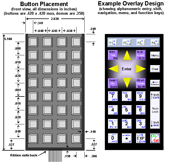
Customizing the Keypad OverlayYou can customize the “look and feel” of your instrument by creating your own graphic to be used over your keypad. Figure 8‑3 shows an example graphic.
Figure 8‑3 Keypad layout showing precise button positions, and a sample design for key layout. The keypad includes a clear plastic overlay which forms a pocket into which you can place a paper graphic. When shipped from the factory, the keypad is loosely attached with tape to the enclosure; the adhesive on the back of the keypad is not used to securely fasten the keypad to the enclosure. This allows you to pull up the keypad and install your own custom graphic. Once you have finalized your keypad design, you can remove the backing on the keypad (exposing the adhesive) and permanently attach the keypad to the enclosure. You can also remove the clear plastic overlay and instead use an adhesived plastic sheet with your own graphic. Figure 8‑3 provides the dimensions of the keypad, showing the precise placement of the buttons. Note that they are not arrayed perfectly evenly; your graphic design should take into account their precise placement. also shows an example overlay design including alphanumeric entry keys, shift and menu keys, navigation keys, and function keys. One key is special: The bottom right corner key is used to turn the handheld on and off. It is directly wired to the handheld’s power circuitry and it is not scanned with the other keypad keys by the keypad driver routines. Your graphic should show this dedicated key as the on/off button. Using the Keypad PocketYou can print a graphic image on ordinary photo paper and insert it into the keypad pocket. We’ve had the best success printing on “Epsom Photo Quality Ink Jet Paper (Matte Finish)” Part Number S041062, or equivalent: 27 lb, ISO 90 brightness (or greater), 4.9 mil, coated paper. Using a thin paper will not interfere with the buttons’ tactile feedback, while much thicker paper stock may. After printing, the image can be cut to size to fit within the pocket, i.e., to 2.350 x 5.050 in., and carefully slid into the pocket. You can also achieve a better finished look if the image is inserted into the keypad pocket slightly underlapping the black border of the keypad’s top clear plastic layer. If so, cut the image slightly larger. To insert it you will need to peel back the pocket’s top clear plastic layer. Peel it back starting at the top – it is pressure-sensitive-adhesived at the side and bottom edges only. Then place the overlay onto the keypad, carefully centering it so that its edges slightly underlap the black borders of the top plastic layer, and carefully aligning its top edge with the top edge of the keypad. Then place the top layer back on, and reseal the pocket by running a finger around the bottom and side edges to reattach the pressure sensitive adhesive. Printing on a Plastic OverlayAlternatively you can print directly on plastic sheets and use them in place of the top layer on the existing keypad. For use as a top layer, the cropped size of your graphic should be 2.630 by 5.180 in. |
Home|Site Map|Products|Manuals|Resources|Order|About Us
Copyright (c) 2006 Mosaic Industries, Inc.
Your source for single board computers, embedded controllers, and operator interfaces for instruments and automation