|
|
The C Programmer’s Guide to the Mosaic HandheldTable of ContentsPART 1 GETTING STARTED Introduction. How to Use This Manual Chapter 1: Getting to Know Your Handheld Instrument Chapter 2: Powering Your Handheld PART 2 PROGRAMMING THE MOSAIC HANDHELD Chapter 4: The IDE: Writing, Compiling, Downloading and Debugging Programs Chapter 5: Making Effective Use of Memory Chapter 6: Real Time Programming Chapter 7: Failure and Run-Time Error Recovery Chapter 8: Programming the Graphical User Interface The Structure Of The GUI Toolkit Transferring Your Images to the Handheld Controller Expanding the GUI Toolkit’s Objects and Methods Customizing the Keypad Overlay PART 3 COMMUNICATIONS, MEASUREMENT, AND CONTROL Chapter 9: Digital and Timer-Controlled I/O Chapter 11: Serial Communications Chapter 12: The Battery-Backed Real Time Clock Chapter 13: Customizing the Handheld's I/O PART 4: REFERENCE DATA |
Chapter 8 Chapter 8: Programming the Graphical User InterfaceThe Graphical User Interface (GUI) Toolkit is a suite of programming tools that gives you the ability to build an informative and interactive graphical user interface to monitor and control your instrument. This chapter Introduces the structure of the GUI Toolkit; Takes you on a step-by-step guide to building your interactive application; and Provides you with detailed descriptions of each component of the GUI Toolkit. The Structure Of The GUI ToolkitA graphical user interface is created from building blocks such as bitmapped images and ASCII strings. These building blocks, or data, must be organized in an intuitive way so users can easily run your instrument. Object oriented concepts are the key to organizing this data and make it easy for you to design and implement your user interface. Object oriented programming allows you to organize data hierarchically based on objects and manipulate the data using methods. With the GUI Toolkit, it is simple to create elementary objects such as graphics that contain bitmapped image data and textboxes that contain ASCII string data. You can load those objects into other objects such as screens so that they can be shown on the display. You can create yet another type of object, a control, which can execute functions that acquire data from a user or actuate hardware when a user touches the keypad. A Closer Look At ObjectsThe two concepts of object oriented programming essential to modern programs with user interfaces are “Objects” and “Events”. An object is an association of properties and methods, and may respond to events. An event is an external action that prompts an object into action. GUI Toolkit objects that can respond to events are called controls. PropertiesProperties describe an object’s physical attributes like its size, location, or image. Objects contain a data structure that holds its properties. Properties generally don’t do anything by themselves; they are more like read/write variables. However, properties may qualify the object’s behavior when the object does do something or has something done to it. Some properties may be read only while others may be read/write. GUI Toolkit properties are always 32-bit numbers and are accessed or modified by calling the methods Get_Property or Set_Property. Set_Property requires a reference to an object, its property, and the new value, while Get_Property requires a reference to an object and its property as parameters and returns the property value. MethodsMethods are actions the object can do or have done to it. Many methods, like Load, are overloaded; that is, they are applicable to several different types of objects. For example, you can load graphics and textboxes into a screen. Overloaded methods allow you to use a single simple syntax with respect to many different objects. EventsEvents are external actions that an object responds to by executing a user defined function called an event procedure. Objects automatically recognize a predefined set of events, it is up to you to decide if and how they respond to those events. You specify the event procedure called when the event happens (or fires) by storing your function into the appropriate property using Set_Property. Event procedures are written, for example, to specify the program actions that occur in response to the press of a key. The GUI Toolkit ObjectsThe following table lists the objects in the GUI Toolkit.
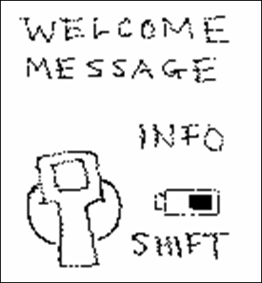
Some of these objects are created when you initialize the GUI Toolkit while others are created by functions that you write. All GUI objects reside in their own task with their own heap and some respond to events. In the next section, we’ll show you how to create your user interface and then how to write your application using the GUI Toolkit. Building Your ApplicationIn this section, we’ll explore the GUI Toolkit in the order in which you would typically build your application. We’ll show you how to: Design and create your user interface on a PC; Transfer the images that you created for your user interface from the PC to the Handheld Controller; Write your application using the demo program as a reference guide; Handle errors; and, Expand the capabilities of the GUI Toolkit. The demo program shows you how to build a multitasking application with four simple screens. The first screen is an alphanumeric keypad example that allows you to enter text and show it on the display. The second screen allows you to adjust the contrast and brightness of the display. The third screen allows you to change the length of each beep that is sounded when you press a key. The fourth screen displays a textbox using a custom font of 8 point Comic Sans. As we describe each part of the GUI Toolkit, we’ll use the alphanumeric keypad screen of the demo to illustrate the important concepts. Designing Your User InterfaceBefore you start coding your application, it’s a good idea to sketch out how you want your user interface to look. Figure 8‑1 shows a rough sketch of the first screen of the demo program. Sketching out your user interface before you start programming will help you to think about how you want your application to be organized and how you want to present information to your user.
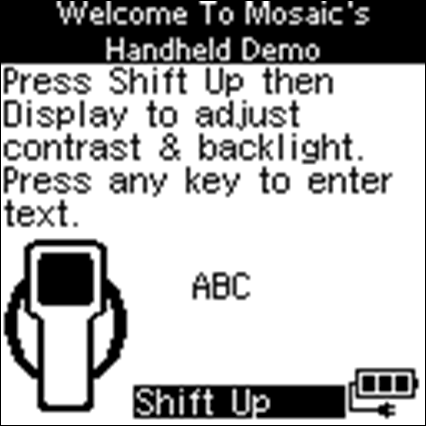
Figure 8‑1 The sketch of the first screen of the demo program. Drawing Your ScreensOnce you’ve sketched out and designed your user interface, you need to create bitmapped images of your interface using an image-editing program. Images may be created using Microsoft Paint, which is included with all versions of Windows. You can also use other image-editing programs such as Corel Draw, Photoshop, and Paint Shop Pro. In this section and throughout this chapter, we provide step-by-step instructions for creating and manipulating images using Photoshop. However, all of the image-editing programs have similar tools and functionality. For example, the pencil tool in Photoshop is simply called the pencil in Paint and the line tool in Photoshop is called the line in Paint. Thus, the steps listed in the examples, although specific to Photoshop, apply to all image-editing programs. To create an image of a screen from your sketch using Photoshop: 1. Create a new file with a width of 128 pixels and a height of 128 pixels, a resolution of 72 pixels per inch, and using the bitmap image mode. 128x128 is the size of the display and the size of a screen. The resolution is not important because it refers to the number of pixels per inch for the monitor. However, the image mode is important and must be set to bitmap if you are using a monochrome display. This configures the image to have one bit per pixel. 2. Draw all lines using the pencil tool with a brush size of one pixel. The line tool, paint brush tool, and airbrush tool are also useful in drawing shapes and patterns. 3. Draw text using the type tool. 4. Save the image as a windows bitmap. A dialog box may appear informing you that some image data, such as printer settings, cannot be saved with this format. This does not effect the image so you can just click on OK. The image that we created based on the sketch in Figure 8‑1 is shown in Figure 8‑2 .
Figure 8‑2 The bitmap image of the first screen of the demo program that was created using Adobe Photoshop. Creating Your ImagesOnce you have created the screens for your user interface, you need to ungroup them. Ungrouping the screens into smaller images will allow you to save space in Flash memory since you don’t want to store images with a lot of white space. To ungroup an image using Photoshop: 1. Select the marquee tool; 2. Left click on the upper left corner of an image you want to ungroup and drag the mouse pointer to the lower right corner of the image. This will create a box with a moving dashed line around the image; 3. Note the location of the upper left corner of the image; this location will be needed when you want to load a graphic containing the image onto a screen; 4. Under the Edit Menu, select the cut option to move the image to the clipboard. The image will disappear from the screen; 5. Under the File Menu, select the create new file option; 6. Name the file, based on the image. The height and width will automatically be set to the height and width of the image that is in the clipboard; 7. Under the Edit Menu; select paste; and, 8. Save the ungrouped image in the Windows bitmap format. The width of an image must be a multiple of 8 pixels and the image must be positioned on an 8 pixel horizontal grid in a screen. Finer horizontal pixel placement and image widths would require bit shifting of each byte of the image every time it is drawn, significantly slowing performance of the GUI Toolkit. There are no limitations on the placement of an image in the vertical direction. The size of an image is limited by its placement and the size of the display. For example, an image placed in the upper left corner (at coordinates 0,0) can be up to 128 pixels wide by 128 pixels tall. However, if the image is moved 8 pixels to the right and 12 pixels down (to coordinates 8,12), the maximum size the image can be is 120 pixels wide by 116 pixels tall. Transferring Your Images to the Handheld ControllerOnce you have ungrouped all the images for your user interface, assemble them into a single directory. Images must be processed before you can use them with the GUI Toolkit; Mosaic’s Image Conversion Program concatenates images into a single text file called an Image Data File. The Image Data File is stored in the same directory as your images and when it is transferred to the Handheld Controller, it stores your image data in RAM and then copies it into Flash. You must transfer the Image Data File using Mosaic’s Terminal Program, to the Handheld Controller before you transfer your application code. For more information on the Image Conversion Program, see the section on the Image Conversion Program . The Image Header FileAn Image Header File is also created with the Image Conversion Program and stored in the same directory as your images. The Image Header File associates the names of your images with the location of their image data in Flash. The Image Header File must be included in your application in order for you to create graphic objects. The following shows the first few lines of the Image Header File used by the demo. The Image Header File defines a few constants, named after the image files display_screen.bmp, sound_screen_bmp, and welcome.bmp shown in the following listing. The constants contain the addresses of the image data in Flash memory on the Handheld Controller. For more information on the memory map of the Handheld Controller see Chapter 4: Making Effective Use of Memory[pkc1]. Listing 8‑1 The first few lines of the Image Header File. #define DISPLAY_SCREEN_BMP 0x7101F36 #define SOUND_SCREEN_BMP 0x102756 . . . #define WELCOME_BMP 0x103497
Coding Your ApplicationOnce you have designed and built the user interface for your application and you have transferred the images to the Handheld Controller, you can start writing the code to animate your instrument. All GUI applications need the following components: The pre-loaded GUI Toolkit driver software; The Image Data and Image Header Files from the Image Conversion Program; An initialization routine that initializes the GUI Toolkit and sets up a task to run your application’s user interface. Routines that create and configure objects; Event procedures that animate controls; Routines that load objects onto screens; and, An endless loop that executes event procedures Each of these components are described in the following sections. The GUI Toolkit Driver SoftwareThe GUI Toolkit driver software is pre-installed on your Handheld Controller. However, you will need to copy the library files (which define constants, structures, and headers for the GUI Toolkit methods) to the same directory as your source code as described below. The GUI Toolkit driver software is provided as a pre-coded modular runtime library, known as a “kernel extension” because it enhances the on-board kernel's capabilities. The library functions are accessible from C and Forth. The kernel extension for the GUI Toolkit is available from Mosaic Industries on the Installation CD. Look in the Demos and Drivers directory, in the subdirectory corresponding to your hardware, in the GUI Toolkit folder. The kernel extension is shipped as a “zipped” file named “packages.zip”. Unzipping it (using, for example, winzip or pkzip) extracts the following files: readme.txt - Provides summary documentation about the library. install.txt - The installation file, to be loaded to COLD-started controller. library.4th - Forth name headers and utilities; prepend to Forth programs. library.c - C callers for all functions in library; #include in C code. library.h - C prototypes for all functions; #include in extra C files. Library.c and library.h are only needed if you are programming in C. Library.4th is only needed if you are programming in Forth. The uses of all of these files are explained below. We recommend that you move the relevant files to the same directory that contains your application source code; the references to the library files in the demo assume the library files are in the same directory as the source code. Using the Driver Code with C Move the library.c and library.h files into the same directory as your other C source code files and use the following directives in your highest level source code file:
#include “library.h” #include “library.c” The library.h contains the prototypes and constants of the GUI Toolkit while library.c contains the code to call the various GUI Toolkit methods. You should include library.c only once in your highest level source code file but include library.h in every additional source file that uses GUI Toolkit constants or functions. Note that all of the functions in the kernel extension are of the _forth type. While they are fully callable from C, there are two important restrictions. First, _forth functions may not be called as part of a parameter list of another _forth function. Second, _forth functions may not be called from within an interrupt service routine unless the instructions found in the file named \fabius\qedcode\forthirq.c are followed. NOTE: If your compiler was purchased before June 2002, you must update the files, qlink.bat and qmlink.bat in your /fabius/bin directory on your installation before using the kernel extension. You can download a zip file of new versions from http://www.mosaic-industries.com/Download/new_qlink.zip The two new files should be placed in c:\Fabius\bin. This upgrade only has to be done once for a given installation of the C compiler.
Using the Image Data and Image Header FilesBefore writing your application code, be sure to transfer the Image Data File, created with the Image Conversion Program, to the Handheld Controller. Then, be sure to include the Image Header File in your application as shown below: Listing 8‑2 The first few lines of the demo program. #include <\mosaic\allqed.h> // Include all of the Mosaic utilities. #include “library.h” // Define prototypes and constants of the GUI Toolkit. #include “library.c” // Code used to call the GUI Toolkit functions. #include “image_header.h” // Include constants that define location of your images
Writing Your Application’s Initialization RoutineThe initialization routine of your application needs to initialize the GUI Toolkit and setup a task to control the GUI Toolkit before any GUI Methods are called. Initialize_GUI must be called before any other GUI method! To initialize the GUI Toolkit, call Initialize_GUI, passing it a heap start address and a heap end address as shown in the demo. Listing 8‑3 Initializing the GUI Toolkit #define GUI_HEAP_START 0x0F3000L #define GUI_HEAP_END 0x0F6FFFL . . void main( void ) { Initialize_GUI ( GUI_HEAP_START, GUI_HEAP_END ); . . }
Initialize_GUI performs several actions: it sets up a heap memory structure for the GUI Toolkit; it sets up and activates a task for the GUI Toolkit; it initializes and starts the timeslicer; and it configures several critical objects, called the GUI Toolkit’s pre-instantiated objects. All GUI objects and their associated properties are stored in a heap accessed only by the GUI Toolkit. This GUI Heap can be located in any contiguous block of RAM (i.e. it may span consecutive pages of RAM) but it is typically placed on page 0x0F from 0x3000 to 0x6FFF as shown in the example above. The size of the heap that is needed by the GUI Toolkit depends on your application. As a benchmark, the demo program uses approximately 8k of heap space. Because all objects are stored in the GUI Heap, it is easy to add, modify, or resize objects without worrying about the specifics of their memory allocation. The GUI Toolkit runs in a stand-alone task called the GUI Task. The GUI Task executes an endless loop that: checks to see if new objects need to be created or existing objects need to be modified; polls the keypad looking for events; checks to see if a user defined event procedure needs to be called (as part of the GUI Timer); and, calls Pause. When an action key is pressed, the GUI Task sends a message indicating that the event procedure should be executed. Service_GUI_Events listens for messages from the GUI Task and executes the appropriate event procedure when commanded. Service_GUI_Events must be included in the infinite loop of a task that you create (separate from the GUI Toolkit’s Task) as shown in the following example. This task should also be in charge of creating and initializing the objects for your application. Listing 8‑4 Servicing GUI Events TASK taskbase; . . void GUI_Monitor ( void ) { Initialize_GUI ( GUI_HEAP_START, GUI_HEAP_END); . while(1) { . . Service_GUI_Events(); Pause(); } } void main( void ) { . BUILD_C_TASK(0, 0, &taskbase); // build task ACTIVATE( GUI_Monitor,&taskbase); // activate task StartTimeslicer(); // starts elapse time clock, enables interrupts Pause(); // start next task immediately }
The GUI Toolkit is a resource whose access must be controlled. Only the GUI Toolkit (running in the GUI Task) polls the keypad, writes to the display, creates objects, or modifies objects. We recommend that you use only one task to run the your application’s user interface so that only one task interacts with the GUI Toolkit. However, if multiple tasks in your application need to use the GUI Toolkit, you must create and use a resource variable to assure that only one task accesses the GUI Toolkit at a time. See the chapter on Real Time Programming for more information on using resource variables. The GUI Task should have an opportunity to run approximately once every 50 milliseconds. Calling the GUI Task more frequently will not improve performance because the GUI Task polls the timeslicer to assure it is not called more than once every 50 milliseconds. Calling the GUI Task less frequently will not cause any errors but may result in sluggish performance. Because the GUI Toolkit polls the timeslicer, the timeslicer must be running or the GUI Toolkit will freeze. The GUI Task takes approximately one millisecond to execute if no events occur, no new object needs to be created, and no existing object needs to be modified. When an event fires, the time the GUI Task takes to execute is proportional to the number of items that are loaded onto the visible screen. For a screen with 15 objects, it will take approximately 5 milliseconds to pass the event to the responsible control. Additional time is required if the responsible control has an image that has to be redrawn. The GUI Toolkit’s Pre-Instantiated ObjectsThe GUI Toolkit has a set of special objects that are created and configured only when you initialize the GUI Toolkit. These special objects are called the pre-instantiated objects because they are instantiated or created before the GUI Toolkit starts it’s task. These objects include the GUI Toolkit itself, display, four predefined screens, four predefined keypads, battery, timer, pen, buzzer, and default font. You can not create additional instances of these objects because they are tied to a specific piece of hardware or unique function of the GUI Toolkit. The GUI Toolkit is itself an object with properties that influence the operation of the GUI Task and all other objects. The GUI Toolkit Object is called the GUI TOOLKIT and has properties that determine how objects such as graphics and controls are loaded into screens, whether events are serviced, and the behavior of the GUI Task when an error occurs. The Display Object is called the GUI_DISPLAY, and is tied to the physical display. Properties of the GUI_DISPLAY control the behavior of the display such as adjusting the contrast or controlling the backlight. The GUI_DISPLAY contains four pre-instantiated screens called GUI_SCREEN0 to GUI_SCREEN3. A property of GUI Screens is their VISIBLE property. Only one of the GUI Screens may be made visible at a time. When it is made visible, the other GUI Screens are automatically made not visible and the display suddenly shows the visible screen’s objects. GUI Screens are the only objects that are shown on the physical display. To show an object like a graphic on the display, the object must be loaded into the visible GUI Screen. The visible screen after Initialize_GUI is called is GUI_SCREEN0. Each GUI Screen has an associated keypad named GUI_KEYPAD0 to GUI_KEYPAD3. A keypad is a collection of keys; the possible types of keys are action keys, data entry keys, and shift keys. Action keys generate events when a user presses the key (press event), holds down the key (hold event), and releases the key (release event). Data entry keys are used to enter numbers, letters, or symbols into textboxes. You can overload data entry keys so that the same key can be used to enter multiple numbers, letters, or symbols. For example, in the demo, the number 9 data entry key is used to enter the number “9” as well as the letters “W”, “X”, “Y”, “Z”, “w”, “x”, “y”, or “z”. Shift keys are used to change the shift state to enable the overloading of data entry keys. The Battery Object is called the GUI_BATTERY, and it is tied to the physical rechargeable batteries. Properties of the GUI_BATTERY include the battery voltage, battery current usage, battery state, and whether the charger is on or off. The Timer Object is called the GUI_TIMER, and it is used to repetitively call user defined event procedures. The GUI_TIMER is useful for calling routines that need to be called every so often to perform tasks like reading the battery. The Pen Object is called the GUI_PEN. This useful tool generates geometric shapes and line drawings on a screen. The GUI_PEN has properties that control how the points and lines are drawn so you don’t have to pass all the optional parameters to the drawing method each time it is called. The Buzzer Object is called the GUI_BUZZER and it is associated with the piezo electric beeper. Properties of the GUI_BUZZER control the length of time of a beep and turn the buzzer on and off. The Default Font Object is called the GUI_FONT and is associated with a custom proportional font that is10-pixels tall. The default font is used to render string data from a textbox onto a screen where it can be shown. Creating New ObjectsThe GUI Toolkit also has other objects, like graphics and textboxes, that you can create using the New_Object method. New_Object requires one input parameter that specifies the type of object you want to create; GRAPHIC, FONT, TEXTBOX, ACTION_KEY, DATA_ENTRY_KEY, SHIFT_KEY, SCREEN, and PLOT are all valid object types. New_Object returns an integer that you store into a variable. This variable (which we call an object reference because it contains a reference to the object) is used to set properties of the object and perform actions on the object like loading the object onto a screen. The following code from the demo, creates a new graphic object and stores its object reference into a variable named graphicWelcome. Later, we’ll set the image of the graphic and then load it into a screen. Listing 8‑5 Creating a New Graphic. int graphicWelcome; . . . void Initialize_Screen0 ( void ) { graphicWelcome = New_Object ( GRAPHIC ); . . . }
Objects can be created but not destroyed. Because objects are stored in the heap, you can only create a finite number of them. Different objects use different amounts of heap space. For example, graphics and fonts only use a few bytes of heap space while plots use hundreds of bytes depending on the size of its buffer. Setting the Property of ObjectsAll objects have their properties set to default values when they are created so that you need to set as few properties as possible to have a fully functional object. However, certain objects like graphics require you to set its image before the graphic can be loaded onto a screen. In the demo, Initialize_Screen0 creates a graphic and then sets it’s image property using a constant defined in the Image Header File. Listing 8‑6 Setting the Property of a Graphic. int graphicWelcome; . . . void Initialize_Screen0 ( void ) { graphicWelcome = New_Object ( GRAPHIC ); Set_Property ( graphicWelcome, IMAGE, WELCOME_BMP ); . . . }
Creating and Initializing ControlsNow that you’re familiar with creating graphic objects, we’ll show you how to create an action key. To create an action key: 1. Use the New_Object method to create an action key and store the object reference to the action key into a variable. By default, the action key will beep when it receives a press event. You can change this behavior by setting the KEYPAD_BEEP property of the keypad containing the action key (GUI_KEYPAD0 in this case) to GUI_FALSE. 2. Initialize any required action key properties such as BLOCK_ON_HOLD. The next section discusses when to use blocking in your application. 3. Define the PRESS_EVENT_PROCEDURE for the action key. Writing event procedures is covered after the next section on blocking. 4. Associate the event procedure with the action key using the Set_Property method. 5. Insert the action key into a keypad using the Insert_Key method. Inserting a key into a keypad associates the key with a screen. When the associated screen becomes visible, the key becomes active (i.e. the key will responded to presses). The key positions are shown in the following table: Table 8‑1 The key positions for a keypad.
The on / off key is tied to power circuitry so it can not be moved or assigned to different function. The following code shows the Initialize_Screen0 function from the demo that illustrates how to create an action key that, when pressed, will beep, and execute an event procedure. Listing 8‑7 Creating and Initializing a Control. int actionkeyFunction1; . . . void Initialize_Screen0 ( void ) { . . . actionkeyFunction1 = New_Object( ACTION_KEY ); Set_Property(actionkeyFunction1, BLOCK_ON_PRESS, GUI_TRUE); Set_Property(actionkeyFunction1, PRESS_EVENT_PROCEDURE, (long) Function1_event_procedure_ptr); // Position the function 1 key to be in the upper left corner of the keypad. Insert_Key ( GUI_KEYPAD0, actionkeyFunction1, 0 ); . . . }
Defining and initializing other controls like data entry keys and shift keys are handled in the same way. Examples of how to define and initialize data entry keys and shift keys are shown in the demo. When To Use BlockingTurning off the service events property of the GUI Toolkit (also called blocking) disables the keypad and keys from changing GUI Toolkit properties. Blocking is required when the state of the GUI Toolkit must remain unchanged for a short time period. Blocking is usually associated with action keys with event procedures that need to read, write, or change properties or calls GUI Toolkit methods. As shown in the previous listing, the block on press property of the action key is set because its event procedure (as shown in the next listing) changes the visible property of a screen. Thus once the action key is pressed, no other keys will be able to change GUI Toolkit properties (so another key that is simultaneously pressed can’t make another screen visible causing a conflict). If you configure an action key to block, it is your responsibility to re-enable the servicing of events in the event procedure. Typically, the re-enabling of events is the last thing you do in an event procedure before exiting. Writing Event ProceduresEvent procedures are functions that you write to animate your controls. Event procedures cannot take any parameters or return any values, but they can set variables and call other GUI methods like Clear and Refresh. In the demo, the event procedure for the Function 1 Action Key changes the visible screen. The following listing shows the code for the action key’s event procedure. Listing 8‑8 Writing the Event Procedure. void Function1_Event_Procedure ( void ) { // Set GUI Screen 3 to be the visible screen. Set_Property ( GUI_SCREEN3, VISIBLE, GUI_TRUE ) ; // The action key associated with this event procedure must be configured to // block on press since the event procedure must change the visible property // of a screen. Re-enable the servicing of events here at the end of the // event procedure. Set_Property ( GUI_TOOLKIT, SERVICE_EVENTS, GUI_TRUE ); } // We need to store the address of the event procedure into a function pointer which // will be used to associate the event procedure with the action key. #include “begin_event_procedure_pointers.h” . . . xaddr (*function1_event_procedure_ptr)(void) = Function1_Event_Procedure; . . . #include “end_event_procedure_pointers.h”
Loading Objects into ScreensThe final step in creating a GUI application is loading the objects onto the screen. To load an object onto a screen, use the Load method. The following code initializes a graphic for GUI_SCREEN0 and then loads it into the screen. Listing 8‑9 Loading a Control into a Screen. void Initialize_Screen0 ( void ) { graphicWelcome = New_Object ( GRAPHIC ); Set_Property ( graphicWelcome, IMAGE, WELCOME_BMP ); Load ( GUI_SCREEN0, graphicWelcome, 0, 0 ); . . . }
We've now shown you how to design and build your user interface, initialize the GUI Toolkit, create and initialize objects, write event procedures, and load objects onto screens. This final section covers how to handle errors that may occur during your application. Handling ErrorsThe GUI Toolkit has extensive error handling and reporting abilities. When an error occurs, an error code is logged and an attempt is made to recover from the error. For example, if you try to load a graphic that contains an image which is 24 pixels wide to the coordinates (112,0), 8 pixels of the image will hang off the edge of the screen (since the width of a screen is 128 pixels). This will generate an X_OUT_OF_RANGE error, and the graphic will instead be loaded to the right-most position on the screen at (104,0). You can read the error code by using the Read_Error method of the GUI Toolkit object. Because only the last error is recorded, you must call Clear_Error after you read the error to prevent servicing the same error more than once. The following code shows how to create a custom error handling and reporting routine: Listing 8‑10 Handling Errors. void Print_Error ( void ) { switch (Read_Error()) { case HEAP_FULL: printf(“Can’t create any more new objects.\n”); break; case X_OUT_OF_RANGE: printf(“X coordinate is out of range.\n”); break; // You would put other error codes and error messages here. } Clear_Error(); // Be sure to clear the error after we read it; // we don’t want to respond to the same error more than once. }
Multiple errors can occur for each GUI Toolkit method but only one can occur at a time. It is up to you to decide if and when you should check for errors. A useful debugging tool that comes with the GUI Toolkit is the property ABORT_ON_ERROR. If true, an error causes the controller to disable interrupts, stop multitasking, and send a descriptive error message to the primary serial port, Serial 1. The error message identifies the calling method and parameters that triggered the error. ABORT_ON_ERROR helps you to quickly identify the source of the error; this is especially useful when developing a complex application. This property should be set to GUI_FALSE for the production version of your application. Expanding the GUI Toolkit’s Objects and MethodsWe understand that each GUI application you write has unique requirements. Although it is possible for you to implement many things like custom plotting routines or drawing geometrical shapes by writing high level code, there maybe a significant performance advantage in our providing pre-packaged objects to you that perform the desired function. Please contact Mosaic Industries about adding additional objects, properties, and methods to the GUI Toolkit. We are planning to add many features to the toolkit to enhance its capabilities; the features you are looking for may already exist. |
Home|Site Map|Products|Manuals|Resources|Order|About Us
Copyright (c) 2012 Mosaic Industries, Inc.
Your source for single board computers, embedded controllers, and operator interfaces for instruments and automation