| Host page: | sbc-single-board-computers:freescale-hcs12-9s12-c-language:instrument-control:pulse-width-modulation-pwm-motor-control |
|---|
| Pulse Width Modulated I/O |
|---|
| 9S12 HCS12 PWM Pulse Width Modulation Tutorial, PWM Generation Using HCS12 Timer Channels, PWM Duty Cycle, PWM Period, PWM Frequency, PWM Signals, Frequency Generator, PWM Generator, PWM Motor Driver, PWM Controller |
|---|
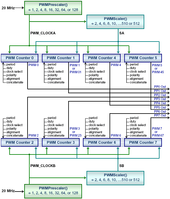
| You can configure 8 channels of 8-bit resolution or 4 channels of 16-bit resolution pulse width modulation (PWM) outputs, using the 9S12 HCS12 timer channels, specifying their PWM duty cycle, PWM period, and PWM frequency with PWM frequencies of a fraction of 1 Hz to 78kHz, or generate lower resolution waveforms at frequencies to 10 MHz. HCS12 9S12 PWM tutorial. PWM controller outputs may control stepper motors, servo-motors, brushless motors, proportional valves, LEDs or actuators. |
|---|
| Image caption: | 9s12-hcs12-pwm-clocks-duty-cycle.png |
|---|
| Image path: | sbc-single-board-computers:freescale-hcs12-9s12-c-language:instrument-control:9s12-hcs12-pwm-clocks-duty-cycle.png |
|---|
| Date | 2012-10-05 08:51 |
|---|
| Filename | 9s12-hcs12-pwm-clocks-duty-cycle.png |
|---|
| Format | PNG |
|---|
| Size | 15KB |
|---|
